137 of 282
M-SV-001-EN Rev. G
Table 4-29 SCR Diode Values
4.19.2.3 Gates Verification
1. Isolate the compressor power as described in Section "1.8 Electrical Isolation" on page 19.
2. Remove the Top Cover. Refer to "4.2.2.1 Top Cover Removal and Installation" on page 57.
3. Using needle-nose pliers, carefully remove the SCR Gate Cable Harness from the SCRs. Refer
to "Figure 4-143 SCR Connections - TTS300/TGS230" on page 134 and "Figure 4-144 SCR
Connections - TTS/TGS/TTH/TGH Rev. F and Earlier (Except TTS300/TGS230)" on page 135.
4. Using a multimeter set for resistance measurements, place the leads on the two (2) gate
terminals. The value should be between 1 to 25Ω.
5. Reverse the leads. The measured value should be the same.
Table 4-30 SCR Gate Resistance Ranges
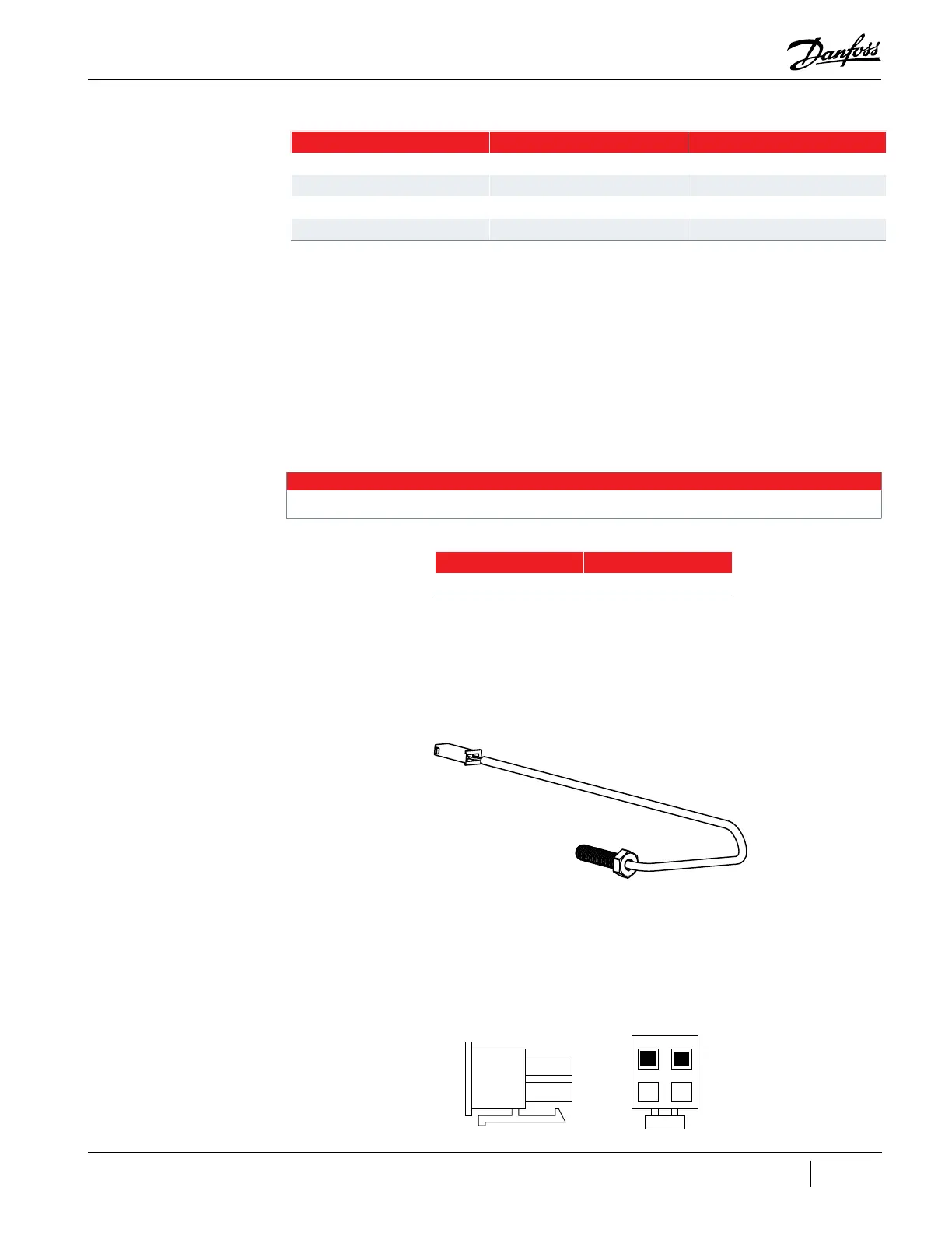
4.19.2.4 SCR Temperature Sensor
This section applies to TTS/TGS Revision G and earlier compressors only. The TTS/TGS Revision H and
TTH compressors do not utilize an SCR Temperature Sensor.
Figure 4-148 SCR Temperature Sensor Assembly
4.19.2.5 SCR Temperature Sensor Verification
1. Isolate the compressor power as described Section "1.8 Electrical Isolation" on page 19.
2. Remove the Service Side Cover. Refer to "4.2.3.1 Service Side Cover Removal and Installation"
on page 58.
3. Disconnect the SCR temperature sensor cable plug (INTER - J17) from the Backplane Board.
Figure 4-149 J17 Connector
Positive (+) Lead Negative (-) Lead Expected Result
1 2 Infinity or Open
1 3 Infinity or Open
2 1 Infinity or Open
3 1 0.3V and 0.45V
NOTE
These values can vary depending on the meter being used. It is important that the values be consistent between SCRs.
SCR Model Range
All models 1 - 25Ω
1 2
3 4
J17

 Loading...


