211 of 282
M-SV-001-EN Rev. G
Table 4-43 Backplane Test Point Values
9. Install the Service Side Cover. Refer to "4.2.3.1 Service Side Cover Removal and Installation" on
page 58.
4.26.3 Backplane Removal and Installation
4.26.3.1 Backplane Removal
1. Isolate compressor power.
2. Wait for the Backplane LEDs to turn off.
3. Remove the Serial Driver. Refer to "4.27.4 Serial Driver Removal and Installation" on page 213.
4. Remove the BMCC. Refer to "4.28.4 BMCC Removal and Installation" on page 217.
5. Remove the PWM. Refer to "4.29.4 PWM Removal and Installation" on page 221.
6. Disconnect and remove all remaining connectors from the Backplane. Refer to "Figure 4-265
Backplane Connections" on page 208.
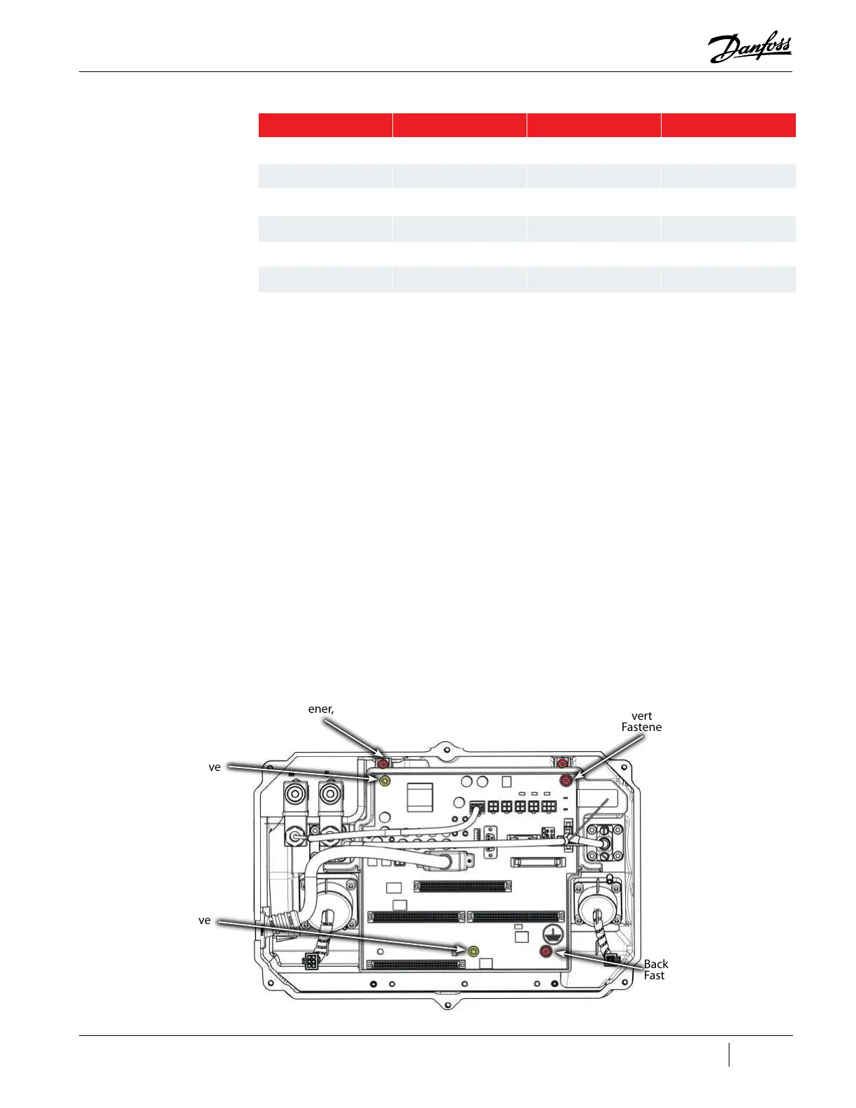
7. Remove the Inverter Ground fastener from the top right of the Backplane to release the
Inverter cable ground ring.
8. Replace the Inverter ground fastener.
9. Remove the three (3) fasteners that secure the Backplane Frame to the housing. Do not remove
the fastener at the top left or bottom center of the Backplane so the circuit board remains in
the frame. Refer to "Figure 4-269 Removing the Backplane".
Figure 4-269 Removing the Backplane
Test Point Test Point Reference DC Voltage Range Minimum Resistance
HV+ HV- 220 to 280 250Ω
+17HV HV- 16.5 to 17.85 28Ω
+24V 0V 22 to 26 9Ω
+15V 0V 14.75 to 15.25 20Ω
-15V 0V -14.75 to -15.25 150Ω
+5V 0V 4.75 to 5.25 8Ω
Do not remove
Inverter Ground
Fastener, M5x10
Backplane Ground
Fastener, M5x25
Do not remove
Backplane
Mounting Fastener,
M5x25
(2 places)

 Loading...


