70 of 282 M-SV-001-EN Rev. G
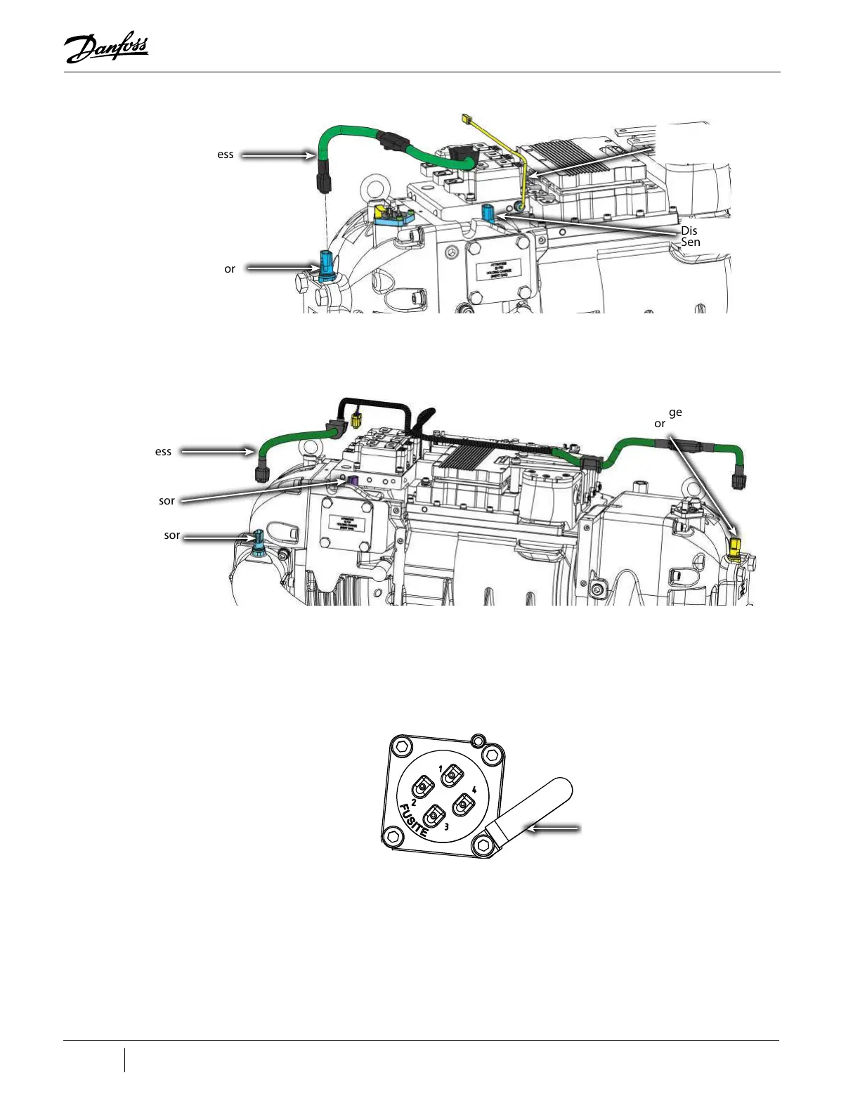
Figure 4-24 Pressure/Temp and SCR Temp Sensor Locations - TTS/TGS
Figure 4-25 Pressure/Temperature Sensors - TTH375/TGH285
8. Disconnect the SCR Manifold Sensor connector.
9. Loosen the M5x16 fastener securing the IGV Connector Clamp and rotate the clamp out of the
way. Refer to "Figure 4-26 IGV Connector Clamp".
10. Remove the harness connector from the IGV Feedthrough.
Figure 4-26 IGV Connector Clamp
11. Remove the DC Capacitor Bus Bar Assembly. Refer to "4.22 DC Capacitor Bus Bar Assembly" on
page 156.
12. Remove the cable harness in stages so the same routing can be followed for the installation.
Compressor Controller Cable Harness Installation
1. Route the cable harness through the hole in the main compressor housing at the service side.
Refer to "Figure 4-27 Cable Passage" on page 71
TTS350 Rev. F Shown
Cable Harness
SCR Temperature
Sensor Cable
Discharge
Sensor
Suction Sensor
Cable Harness
Suction Sensor
Discharge
Sensor
Interstage Sensor
Cable Clip

 Loading...


