90 of 282 M-SV-001-EN Rev. G
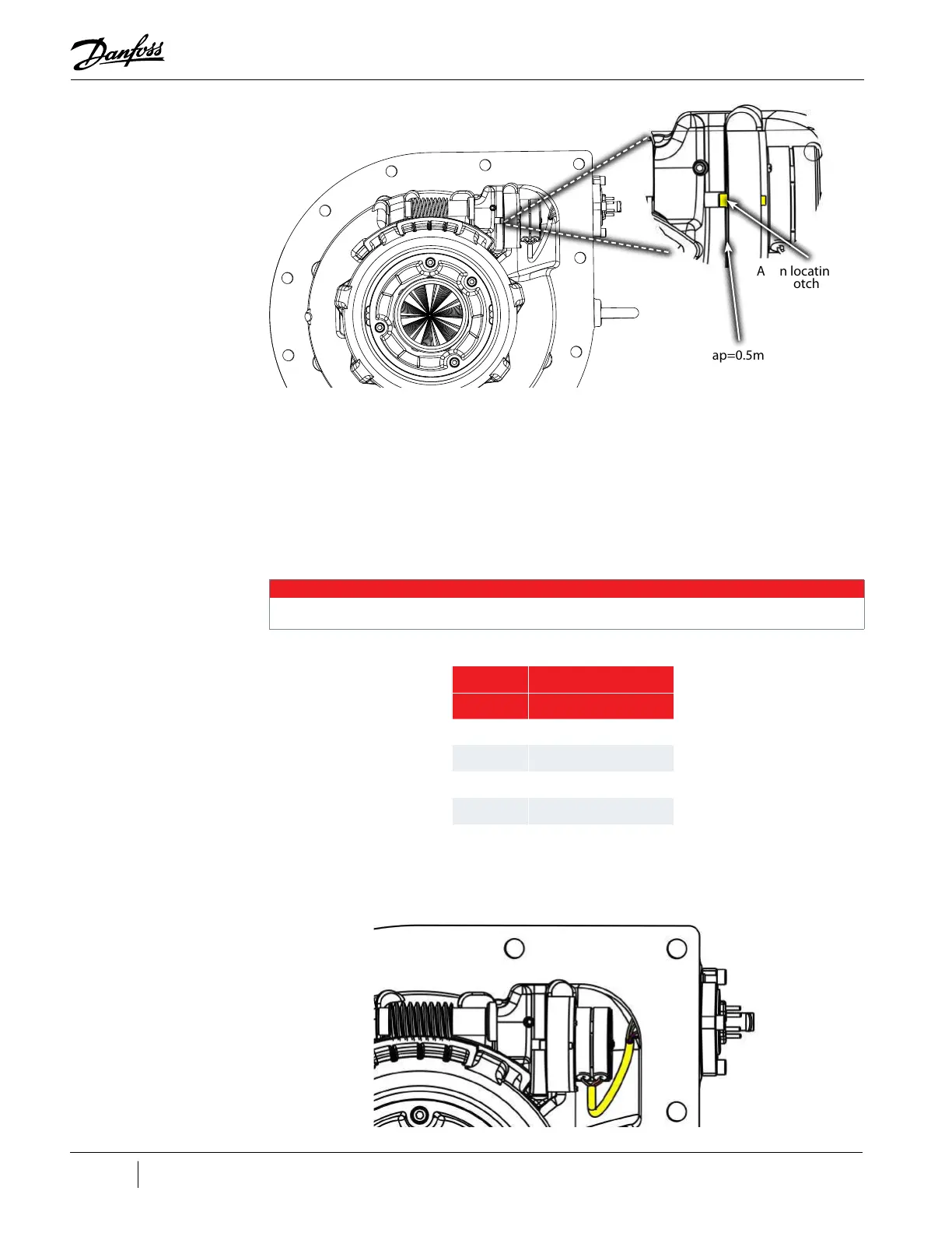
Figure 4-69 IGV Motor Alignment
16. Put one (1) drop of threadlocker (Loctite 243 blue or equivalent) on the threads of the small set
screw. While pushing in, on the backside of the motor, secure the worm gear to the flat surface
of the motor shaft using a 2.5 mm hex bit. Rock the motor backwards and forwards while
tightening to ensure full and correct engagement of the screw. Torque the set screw to 5Nm
(44 in.lb.). Refer to "Figure 4-67 IGV Worm Gear Alignment" on page 89.
17. Clean, lubricate, and install the O-ring on the Feed Through before connecting the wires.
18. Insert the motor wires onto the Feed Through pins in accordance with "Table 4-16 IGV
Feedthrough Pin to Wire Reference". Also reference your notes from removal.
NOTE
The colors associated with each pin could vary, so be sure to refer to notes taken during removal.
Table 4-16 IGV Feedthrough Pin to Wire Reference
19. Position the wires as shown in "Figure 4-70 Motor Wire Position" and "Figure 4-71 IGV Motor
Wires Connected".
Figure 4-70 Motor Wire Position
Align locating pin
with notch
Gap=0.5mm
All Except TT300N
Color Pin Number
Red 1
Gray 2
Yellow 3
Black 4

 Loading...


