227 of 282
M-SV-001-EN Rev. G
4.30.4.2 Bearing Power Feedthrough Installation
1. If necessary, clean both mating surfaces with a lint-free cloth.
2. Apply Super-O-Lube on the new O-ring.
3. Install the lubricated O-ring onto the new feedthrough.
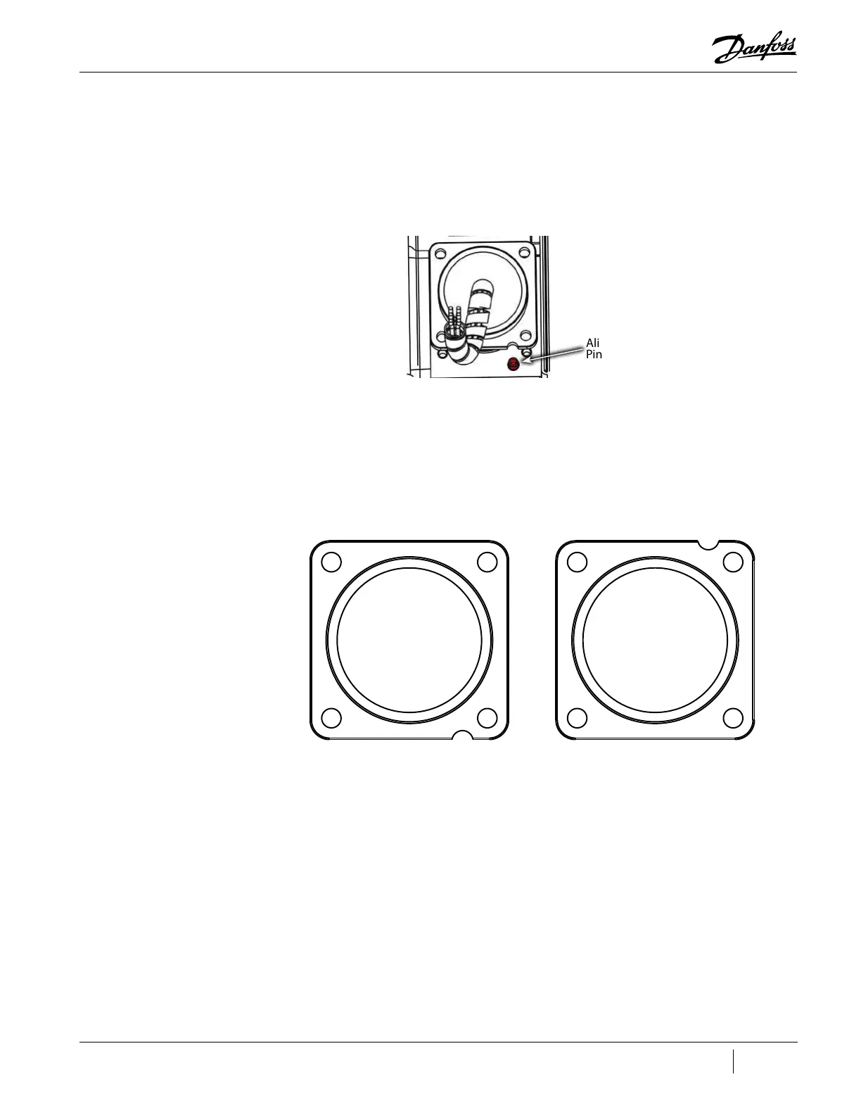
4. Install the new feed through into the compressor housing. Check connector orientation with
the Alignment Pin as well as the internal female connector of the bearing.
Figure 4-288 Bearing Power Feedthrough Alignment Pin
5. Finger-tighten the four (4) M5x16 fasteners and then torque in a crisscross pattern to 3 Nm
(27 in. lb.) and then to a final torque of 5 Nm (44 in.lb.). Refer to "Figure 4-289 Bearing Power
Feedthrough Torque Sequence".
Figure 4-289 Bearing Power Feedthrough Torque Sequence
6. Leak test and evacuate in accordance with standard industry practices.
7. Carefully install the PWM. Refer to "4.29.4 PWM Removal and Installation" on page 221.
8. Plug the cable harness back into the 4-pin feed through and 6-pin feed through.
9. Carefully, install the BMCC. Refer to "4.28.4 BMCC Removal and Installation" on page 217.
10. Carefully, install the Serial Driver. Refer to "4.27.4 Serial Driver Removal and Installation" on
page 213.
11. Install the Service Side Cover. Refer to "4.2.3.1 Service Side Cover Removal and Installation" on
page 58.
12. Install the top covers. Refer to "4.2 Compressor Covers" on page 56.
13. Return the compressor to normal operation.
Alignment
Pin
Front Radial Bearing Power
Feedthrough
31
4
2
Rear Radial and Axial Bearing Power
Feedthrough
2
4
1 3

 Loading...


