219 of 282
M-SV-001-EN Rev. G
The Backplane provides the PWM with +5VDC with respect to 0VDC, along with +17VDC and HV+ (at
250VDC) both with respect to HV-.
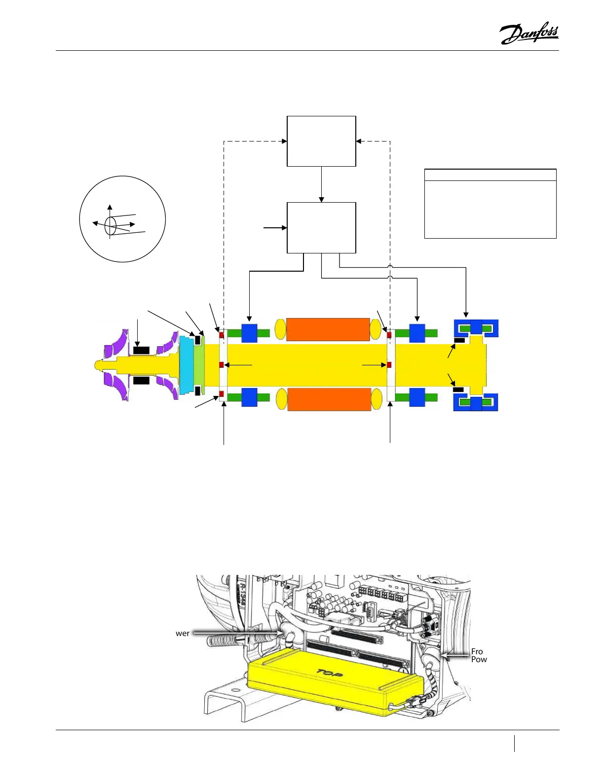
Figure 4-279 Bearing Control Signal Flow
4.29.2 PWM Connections
J1 on the Backplane is the PWM connection port. The PWM heat sink is secured with fasteners to the
compressor housing below the Backplane.
The 6-pin/wire connects to the rear (left) bearing power feed through. The 4-pin/wire connects to the
front (right) bearing power feed through. Refer to "Figure 4-280 Bearing Power Feed Throughs and
PWM Connection Port" for an illustration of a Major Revision "F" and later compressor.
Figure 4-280 Bearing Power Feed Throughs and PWM Connection Port
Impellers
Z‐axis
Position
Sensor
SensorRing
Front
Radial
Bearing
Motor
SensorRing
Rear
Radial
Bearing
Axial
Bearing
X‐axis
Position
Sensor
X‐axis
Position
Sensor
Touchdown
Bearings
Touchdown
Bearings
Target
Sleeve
Y‐axis
Position
Sensor
Y‐axis
Position
Sensor
Channels
Fx,Fy
Channels
Rx,Ry
ChannelAxi
250VDC
PositionCommand
Signals
Bearing‐Motor‐
Compressor
Controller(BMCC)
Bearing
PWM
Amplifier
PositionFeedbackPositionFeedback
Axis Be aring Chann el
X FrontRadial Fx
Y FrontRadial Fy
X RearRadial Rx
Y RearRadial Ry
Z Axi al Axi
ChannelAssignments
Shaftaxesmonitored
bypositionsensors
Y
X
Z
Shaft
Rear Radial and
Axial Bearing Power
Feedthrough
Front Radial Bearing
Power Feedthrough

 Loading...


