177 of 282
M-SV-001-EN Rev. G
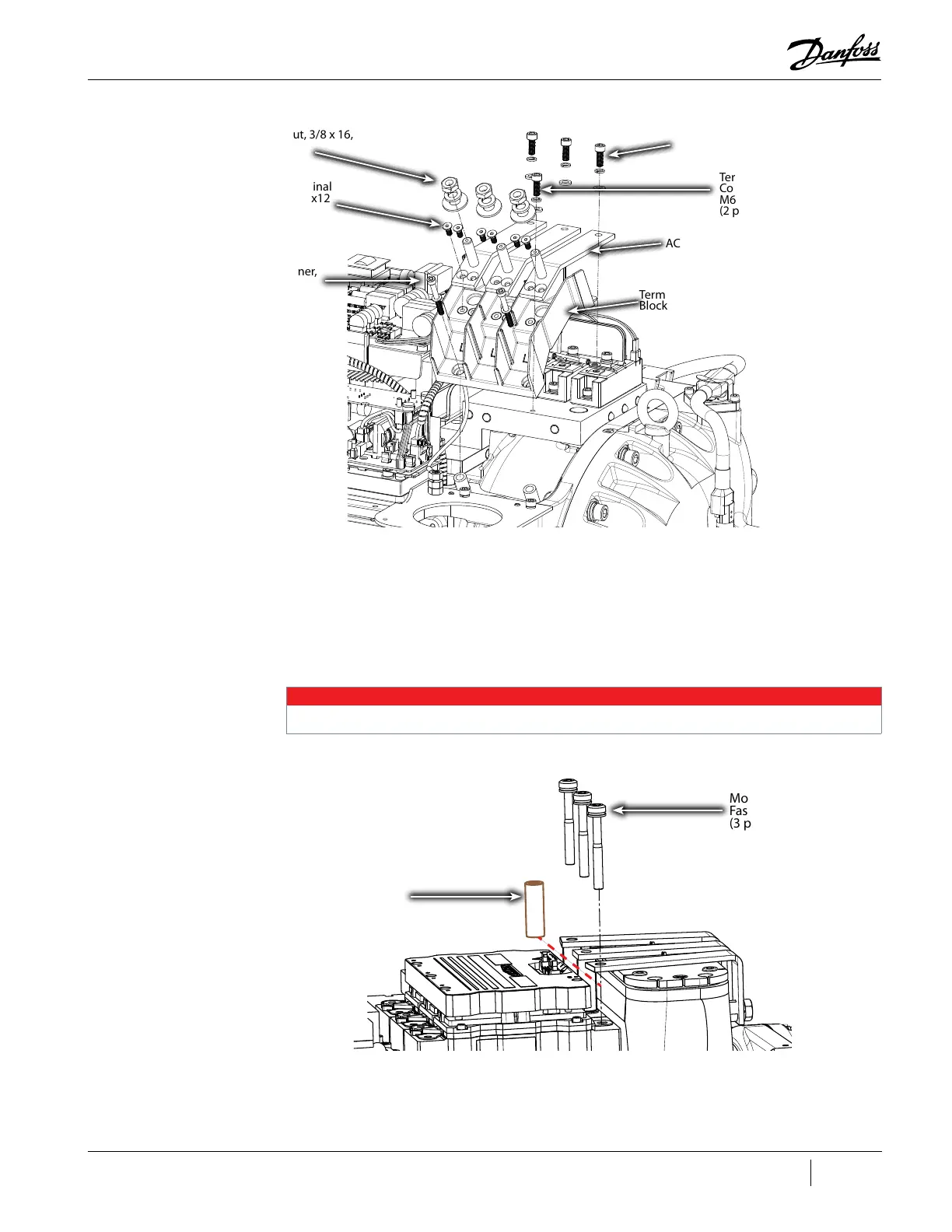
Figure 4-216 Input Terminal Block Removal - TTS/TGS/TTH/TGH Rev. H (Except TTS300/TGS230)
4. Remove the DC Capacitor Bas Bar Assembly. Refer to "4.22.3 DC Capacitor Bus Bar Assembly
Removal and Installation".
5. Remove the three (3) M8x70 Motor Bus Bar fasteners from the Inverter. Refer to "Figure 4-217
Inverter Copper Tube Removal - TTS/TGS/TTH/TGH (Except TTS300/TGS230)" on page 177 for
this and the following step.
6. Slide out all three (3) Inverter Copper Tubes.
Figure 4-217 Inverter Copper Tube Removal - TTS/TGS/TTH/TGH (Except TTS300/TGS230)
7. Loosen the M5x16 IGV Feedthrough fastener that secures the Retainer Clip and rotate the clip
to allow for the connector to be removed. Refer to "Figure 4-218 Retainer Clip Rotation".
AC Bus Bars
Mains Input Nut, 3/8 x 16,
(3 places)
Terminal
Block
AC Bus Bar to Terminal
Block Fastener, M5x12
(6 places)
Terminal Block to
Compressor Fastener,
M5x45,
(2 places)
AC Bus Bar to SCR
Fastener, M8x20,
(3 places)
Terminal Block to SCR
Cooling Plate Fastener,
M6x16,
(2 places)
NOTE
It is not necessary to completely remove the Motor Bus Bars.
Motor Bus Bar
Fastener, M8x70
(3 places)
Inverter Copper
Tube
(3 places)

 Loading...


