226 of 282 M-SV-001-EN Rev. G
5. Install the cable to J10 on the Backplane. Ensure that plug is inserted in correct polarity. Refer
to the locating keys on the plug and slots in the connector. Gently squeeze the connector
retainers to snap the connectors in place.
6. Install the 9-pin connector at the Rear Bearing Sensor Feedthrough and tighten the fasteners.
7. Wipe dielectric grease liberally over the 9-pin connector to seal from moisture ingress.
8. Install the ground wire to J11 or J12 on the Backplane.
9. Install the cable to J9 on the Backplane. Ensure that plug is inserted in correct polarity. Refer
to the locating keys on the plug and slots in the connector. Gently squeeze the connector
retainers to snap the connectors in place.
10. Carry out bearing calibration after replacing either cable. Refer to "5.3 Bearing Calibration" on
page 250.
4.30.4 Bearing Power Feedthrough Removal and Installation
The steps depicted in this section will apply to either the front or rear feedthrough.
4.30.4.1 Bearing Power Feedthrough Removal
1. Isolate compressor power as described in Section "1.8 Electrical Isolation" on page 19.
2. Isolate the compressor and recover the refrigerant according to industry standards. Refer to
"3.1 Refrigerant Containment" on page 41.
3. Remove the Service Side Cover. Refer to "4.2.3.1 Service Side Cover Removal and Installation"
on page 58.
4. Pull the Serial Driver Module out of its slot. Make sure you do not damage the connector pins.
Keep the module in a safe place. Refer to "4.27.4 Serial Driver Removal and Installation" on
page 213.
NOTE
Refer to "1.9 Handling Static Sensitive Devices" on page 20 or proper ESD handling of electronic components.
5. Pull the BMCC out of its slot. Make sure you do not damage the connector pins. Keep the BMCC
in a safe place. Refer to "4.28 BMCC" on page 214.
6. Unplug the cable harness from the 4-pin feed through and the 6-pin feed through.
7. Remove the three (3) M5x10 fasteners and pull the Bearing PWM out of its slot. Make sure
you do not damage the connector pins. Keep the PWM in a safe place. Refer to "4.29.4 PWM
Removal and Installation" on page 221.
8. Remove the four (4) M5x16 fasteners that secure the feed through.
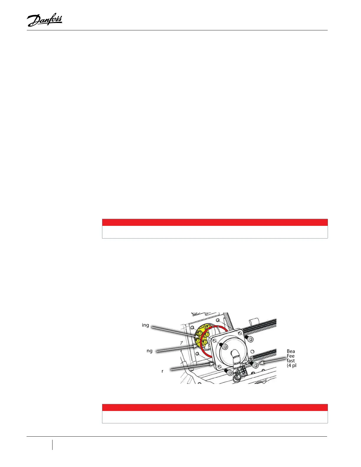
Figure 4-287 Bearing Power Feedthrough Assembly
9. Remove the Feedthrough
NOTE
Small pliers such as needle-nose, may be required to remove the feedthrough.
Bearing Power
Feedthrough
Internal
Female Bearing
Connector
O-ring
Bearing Power
Feedthrough
fastener, M5x16
(4 places)

 Loading...


