130 of 282 M-SV-001-EN Rev. G
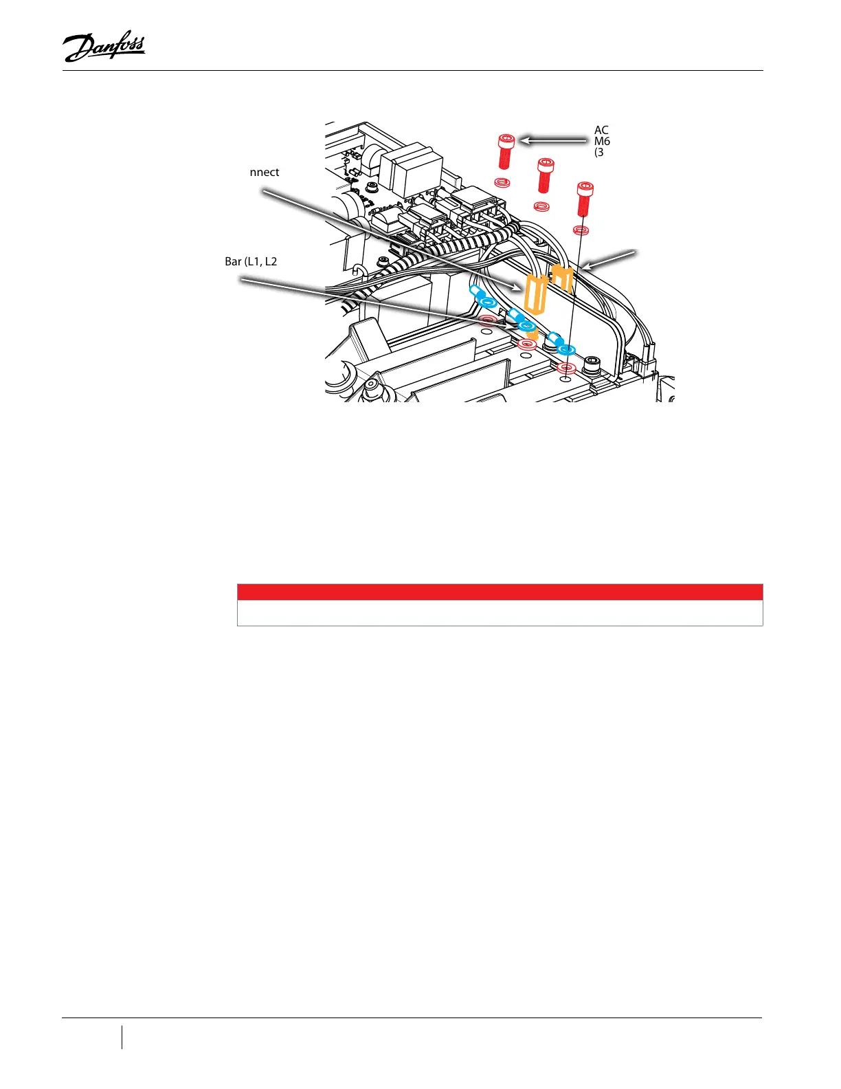
Figure 4-138 AC Input Ring and DC Spade Connector Removal - TTS/TGS/TTH/TGH Rev. H (Except TTS300/TGS230)
4. Remove the DC-DC Connections.
a. If the DC-DC is the potted style, remove connectors J1 and J4. Refer to "Figure 4-134 DC-
DC Connectors (Potted)" on page 128.
b. If the DC-DC is the open-frame style, only J1 will need to be removed. Refer to "Figure
4-133 DC-DC Connectors (Open Frame)" on page 127.
5. Remove the Soft Start AC/DC Harness from the Soft Start.
a. For compressors with the Closed-Top Soft Start, remove the J1 and J7 (if equiped)
connector. Refer to "Figure 4-135 Closed-Top Soft Start J1 and J7 Removal" on page 128.
NOTE
Compressors utilizing the open frame DC-DC design do not utilize the J7: Trigger Signal connector.
b. For compressors with the Open-Top Soft Start, remove connectors J1 and J8. Refer to
"Figure 4-136 Open-Top Soft Start J1 and J8 Removal".
6. Remove the harness.
AC Bus Bar Fastener,
M6x16
(3 places)
AC/DC Bus Bar (L1, L2, & L3)
Terminals
(3 places)
-DC Spade Connector
+DC Spade Connector

 Loading...


