236 of 282 M-SV-001-EN Rev. G
7. Install the top covers. Refer to "4.2 Compressor Covers" on page 56.
8. Return the compressor to normal operation.
4.33.4 Pressure/Temperature Sensor Removal and Installation
4.33.4.1 Suction Pressure/Temperature Sensor Removal
1. Isolate the compressor power.
2. Isolate the compressor and recover the refrigerant according to industry standards. Refer to
"3.1 Refrigerant Containment" on page 41.
3. Disconnect the sensor connector.
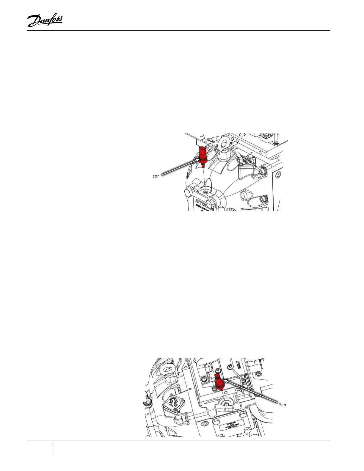
4. Using a deep 15/16" socket, remove the sensor from the IGV Housing Assembly.
Figure 4-305 Suction Pressure/Temperature Sensor Removal
4.33.4.2 Suction Pressure/Temperature Sensor Installation
1. Check and clean the O-ring, housing thread, and O-ring sealing surface in the IGV Housing.
2. Apply lube to O-ring.
3. Insert the sensor and engage the first few threads by hand.
4. Using a deep 15/16" socket, tighten the sensor to 10 Nm (7 ft.lb).
5. Reconnect the sensor connector.
6. Leak test and evacuate in accordance with standard industry practices.
7. Return the compressor to normal operation.
4.33.4.3 Discharge Pressure/Temperature Sensor Removal
1. Isolate the compressor power as described in Section "1.8 Electrical Isolation" on page 19.
2. Recover the refrigerant according to industry standards.
3. Disconnect the sensor connector.
4. Using a deep 15/16" socket, remove the sensor from the compressor housing.
Figure 4-306 Discharge Pressure/Temperature Sensor
Sensor
Sensor

 Loading...


