84 of 282 M-SV-001-EN Rev. G
4. Isolate the compressor and recover the refrigerant according to industry standards. Refer to
"3.1 Refrigerant Containment" on page 41.
5. Remove the 12 M10x40 fasteners that secure the IGV Housing Assembly to the compressor
housing and pull the housing away from the compressor. See "Figure 4-53 IGV Housing
Removal".
Figure 4-53 IGV Housing Removal
4.10.3.2 IGV Assembly Removal
1. Remove the IGV Housing Assembly.
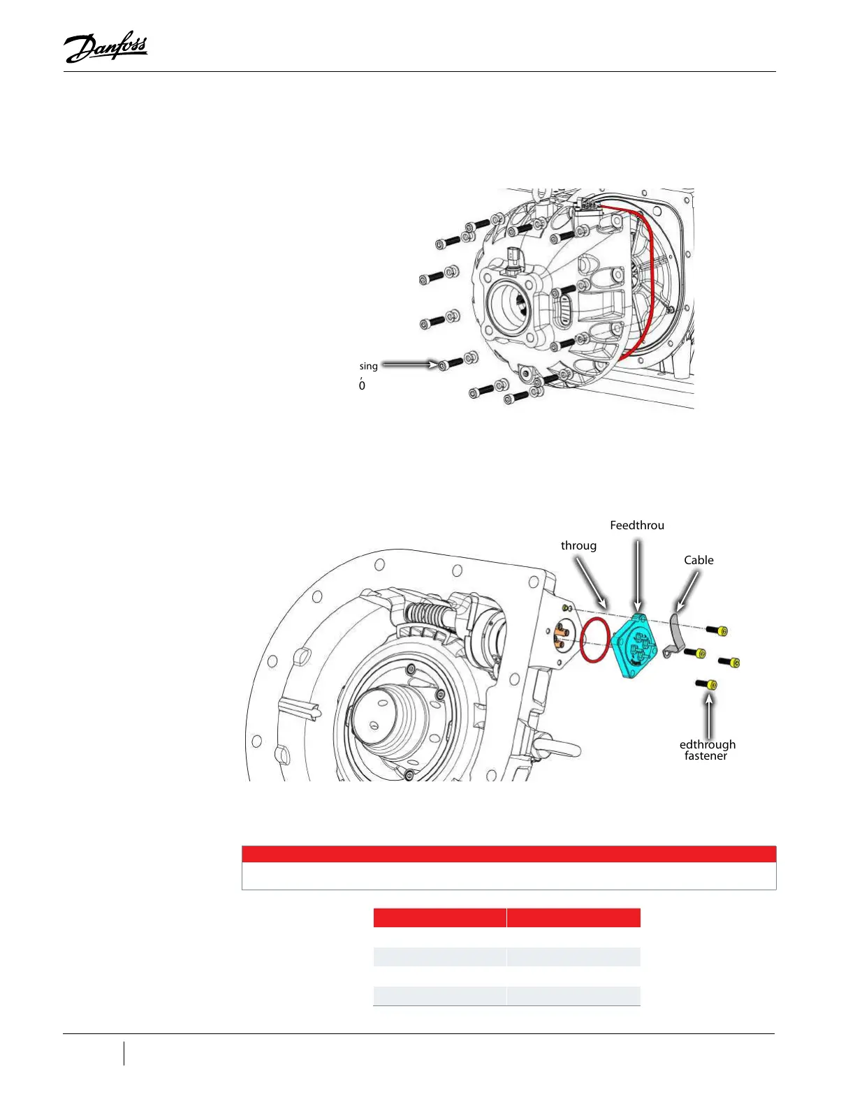
2. Remove the four (4) M5x16 fasteners and separate the four-pin Feedthrough from the IGV
Housing. Refer to "Figure 4-54 IGV Feedthrough Removal".
Figure 4-54 IGV Feedthrough Removal
3. Disconnect the four (4) wires from the four-pin Feed Through. Note and record position of wire
colors to their corresponding pins. Expected: 1 = Red, 2 = Gray, 3 = Yellow, and 4 = Black. Refer
to "Table 4-15 IGV Feedthrough Wiring Order".
NOTE
The colors associated with each pin could vary, so be sure to identify those on the respective compressor.
Table 4-15 IGV Feedthrough Wiring Order
IGV Housing
Fastener,
M10x40
(12 places)
Cable Clip
IGV Feedthrough
M5x16 fastener
(4 places)
IGV Feedthrough
IGV Feedthrough
O-ring
Color Pin #
Red 1
Gray 2
Yellow 3
Black 4

 Loading...


