63 of 282
M-SV-001-EN Rev. G
4.4 Compressor Interface Module
The Compressor Interface Module (CIM), also referred to as the Compressor I/O Board, allows the
user to control the compressor and allows the compressor to return status and sensor information to
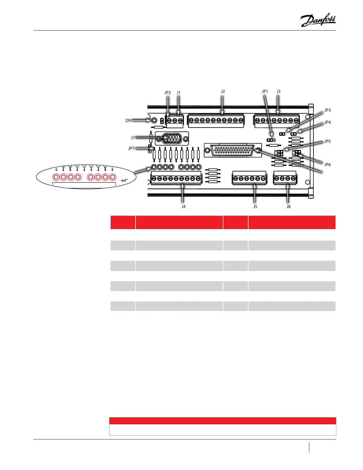
the user. See "Figure 4-18 Compressor Interface Module Ports & Jumpers" for I/O board connection
locations.
Figure 4-18 Compressor Interface Module Ports & Jumpers
Table 4-8 CIM Ports and Jumpers
4.4.1 Compressor Interface Module Connection Descriptions
J1 – RS-485 external communication port
• Jumper JP2 required at end of Modbus line
J2 – Input/output
• DEMAND – Pin 1 & 2 – Analog input to drive compressor (0-10V)
• I/LOCK – Pin 3 & 4 – Interlock safety switch: must be part of a closed circuit to start compressor
• STATUS – Pin 5 & 6 – Output; closed circuit: compressor in normal operation; open circuit:
compressor in alarm condition.
• SPEED – Pin 7 & 8 – compressor motor speed output (0-5V = 10,000 RPM/volt)
NOTE
No longer available for compressors running BMCC firmware versions CC3.0 and later.
D9
J7
JP3
JP4
JP5
JP6
JP7
JP2
J1
J2 J3JP1
J6
J8J5
J4
No. Component No. Component
J1 RS-485 Communication Port JP1 Analog Output Voltage
J2 Input/Output JP2 MODBUS Terminator
J3 Input/Output JP3 Entry
J4 EXV1 and EXV2 Control JP4 Leave
J5 Liquid Level Input JP5 LIQ LEV1
J6 RS232 I/O Cable Connection JP6 LIQ LEV2
J7 RS232 External Communication Port JP7 J7 Power
J8 External Sensor Inputs

 Loading...


