200 of 282 M-SV-001-EN Rev. G
11. Connect the two (2) connectors to the thermistor sensor feedthrough. Refer to "Figure 4-254
Connection to Stator".
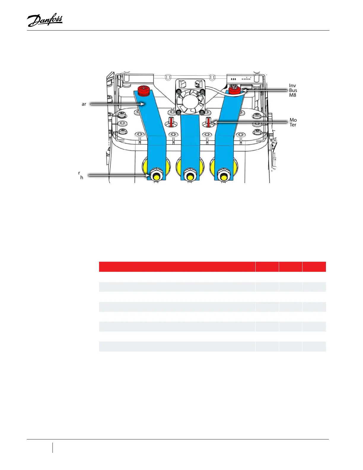
Figure 4-254 Connection to Stator
12. Install the Motor Bus Bars. Refer to "4.24.5 Motor Assembly Removal and Installation" on page
193.
13. Install the Soft Start. Refer to "4.15.3 Soft Start Removal and Installation" on page 112.
14. Install the top covers. Refer to "4.2 Compressor Covers" on page 56.
15. Return the compressor to normal operation.
4.24.5.9 Motor Assembly Torque Specifications
Table 4-38 Motor Assembly Torque Specifications
High Power
Feedthrough
Motor Bus Bar
Motor Thermistor
Terminals
Inverter to Motor
Bus Bar fastener,
M8x70
Description Nm Ft.Lb. In.Lb.
Soft Start Mounting fastener, M5X15 5 - 44
Cover Plate fastener,
M8x25
18 13 159
High-Power Feedthrough (both styles) 22 16 195
Inverter to Motor Bus Bar fastener, M8x70 14 10 124
Motor Bus Bar to Feedthrough Fastener (PPS Feedthrough) 14 10 124
Motor Bus Bar to Feedthrough Nut (Stainless-Steel Feedthrough) 15.5 11.5 137
High-Power Feedthrough Screw to Ring Terminal (PPS Feedthrough) 14 10 124
High-Power Feedthrough Nut to Ring Terminal (Stainless-Steel Feedthrough) 15.5 11.5 137
Cover Fastener 1.5 - 13

 Loading...


