203 of 282
M-SV-001-EN Rev. G
NOTE
J4 for the Potted DC-DC is not shown
4.25.4 DC-DC Harness Removal and Installation
4.25.4.1 DC-DC Harness Removal
1. Isolate the compressor power as described in Section "1.8 Electrical Isolation" on page 19.
2. Remove the Service Side Cover. Refer to "4.2.3.1 Service Side Cover Removal and Installation"
on page 58.
3. Disconnect the two (2) motor thermistor connections.
4. Disconnect the 24 and 250VDC output from the DC-DC. Refer to "Figure 4-258 Potted DC-DC"
and "Figure 4-259 Open Frame DC-DC" for further details.
5. Remove the Soft Start Temperature Harness Connector. The two (2) different Soft Start variants
have a change in these connectors.
a. For Closed-Top Soft Starts, disconnect the J9 connector. Refer to "Figure 4-102 Closed-Top
Soft Start J9 Connector".
b. For Open-Top Soft Starts, disconnect the J7 connector. Refer to "Figure 4-107 Open-Top
Soft Start J7 Connector" on page 114.
6. Carefully cut any cable ties that may be securing the cable harness in place.
7. Disconnect J4, J20, J22, and J24 from the Backplane. Refer to "Figure 4-265 Backplane
Connections" on page 208.
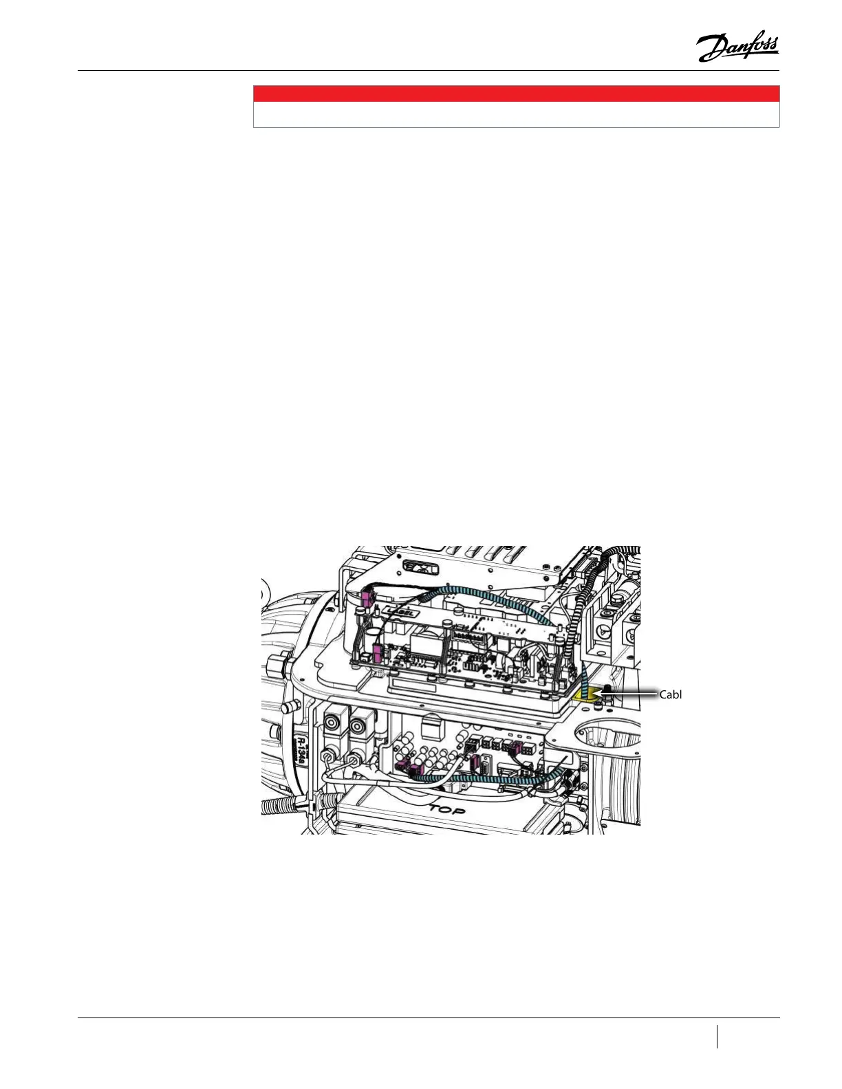
8. Carefully pull the harness through the cable passage and remove. Refer to "Figure 4-257 DC-
DC Harness Routing" on page 203.
Figure 4-257 DC-DC Harness Routing
4.25.4.2 DC-DC Harness Installation
1. Carefully insert the harness into the cable passage.
2. Connect J4, J20, J22, and J24 to the Backplane. Refer to "Figure 4-265 Backplane Connections"
on page 208.
3. Connect the Soft Start Temperature Harness Connector, J9 or J7, to the Soft Start.
4. Connect the 24VDC and 250VDC output from the DC-DC. Refer to "Figure 4-258 Potted DC-DC"
on page 204 and "Figure 4-259 Open Frame DC-DC" on page 204 for further details.
Cable Passage
TTS300 Shown

 Loading...


