208 of 282 M-SV-001-EN Rev. G
4.26.2 Backplane Connections and Test Points
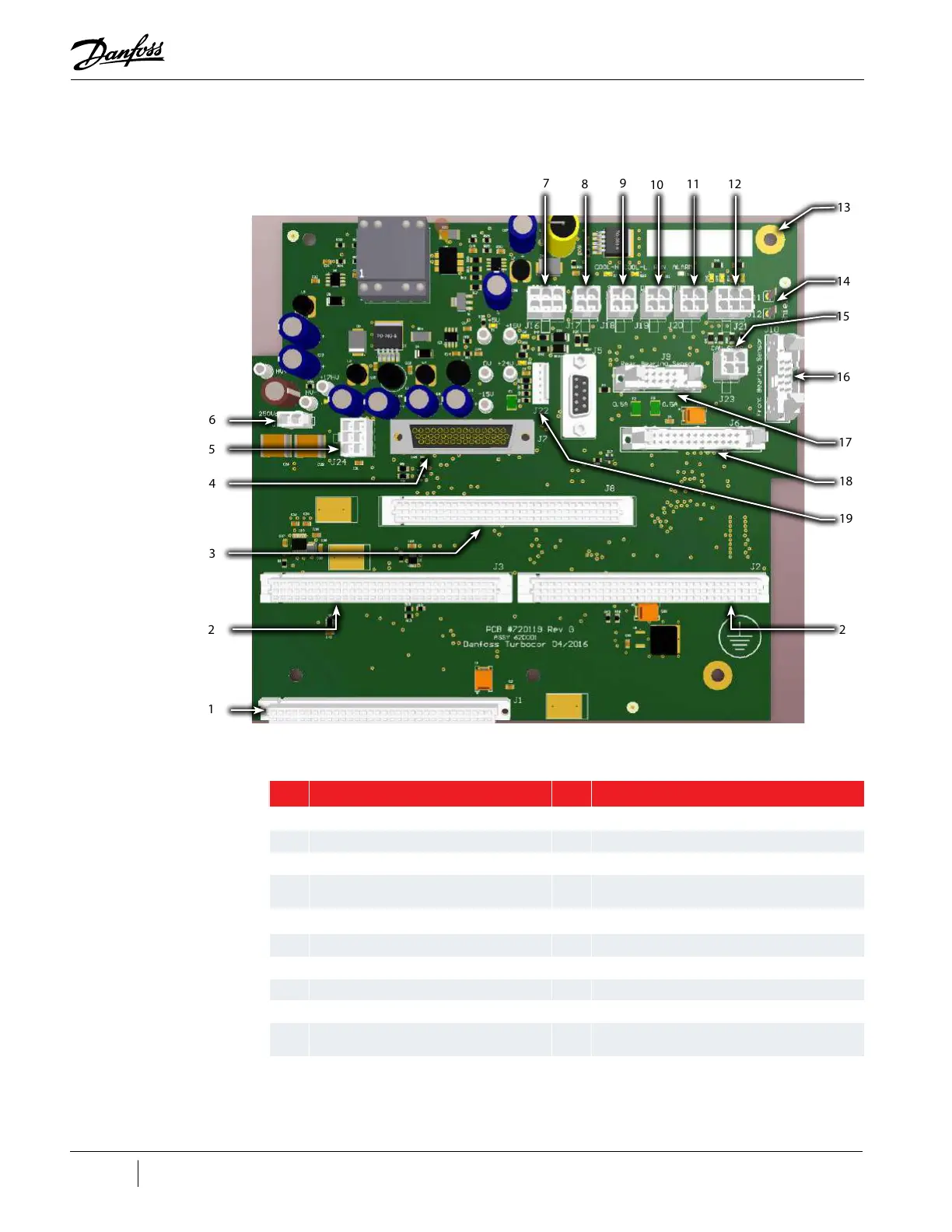
The Backplane connections and test points are indicated in "Figure 4-265 Backplane Connections" and
"Figure 4-266 Backplane Test Points" on page 209.
Figure 4-265 Backplane Connections
Table 4-40 Backplane Connections
7
1
2 2
3
4
5
6
10
11 12
13
14
15
16
17
18
19
9
8
No. Component No. Component
1 J1: PWM Connection Port 11 J20: Motor-Winding Sensor Port
2 J2 and J3: BMCC Connection Port 12 J21: IGV Motor Control Port
3 J8: Serial Driver Connection Port 13 Inverter Ground Screw
4 J7: I/O Cable Connection 14
J11 and J12: Rear Bearing Sensor Cable to Ground
(either may be used)
5 J24: Input of +24VDC from DC-DC 15 J23: Cavity Sensor Input
6 J4: Input of +250VDC From DC-DC 16 J10: Front Bearing Sensor Input
7 J16: Motor-Cooling Solenoids Control Port 17 J9: Rear Bearing Sensor Input
8 J17: SCR Temperature Sensor Port 18 J6: Inverter Connection Port
9 J18: Suction Temperature/Pressure Sensor Port 19 J22: Soft Start Temperature Sensor
10
J19: Discharge Temperature/Pressure Sensor
Port

 Loading...


