230 of 282 M-SV-001-EN Rev. G
5. Remove the BMCC. Refer to "4.28.4 BMCC Removal and Installation" on page 217.
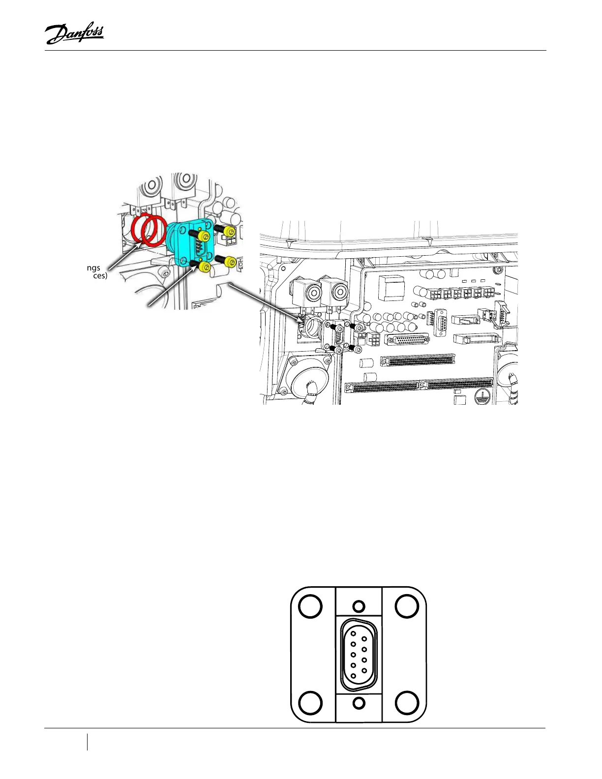
6. Remove the bearing sensor cable from the 9-pin feed through. Refer to "Figure 4-292 Bearing
Sensor Feed Through Removal".
7. Using a hex socket, remove the four (4) M5x16 fasteners that secure the 9-pin feed through.
Refer to "Figure 4-292 Bearing Sensor Feed Through Removal".
8. Carefully remove the 9-pin feed through. It may be necessary to use needle-nose pliers to
grasp the feed through. Do not use a screwdriver to pry the feed through out of the housing.
Figure 4-292 Bearing Sensor Feed Through Removal
4.31.5.2 Bearing Sensor Feedthrough Installation
1. Using a lint-free cloth, clean the mating surface on the compressor housing.
2. Verify that the new O-rings and 9-pin feed through are clean. If not, wipe off any contaminants
with a lint-free cloth.
3. Apply O-lube on each of the new O-rings.
4. Install the new O-rings onto the new 9-pin feed through.
5. Install the new 9-pin feed through.
6. Secure the feed through with the four (4) M5x16 fasteners. Finger-tighten and then follow the
torque sequence shown in "Figure 4-293 Bearing Sensor 9-Pin Feedthrough Connector Torque
Sequence" and torque to 3 Nm (2.2 ft.lb.). Torque the fasteners a final time to 5 Nm (3.7 ft.lb.).
Figure 4-293 Bearing Sensor 9-Pin Feedthrough Connector Torque Sequence
O-rings
(2 places)
M5x16
fastener
(4 places)
2
4
1 3

 Loading...


