135 of 282
M-SV-001-EN Rev. G
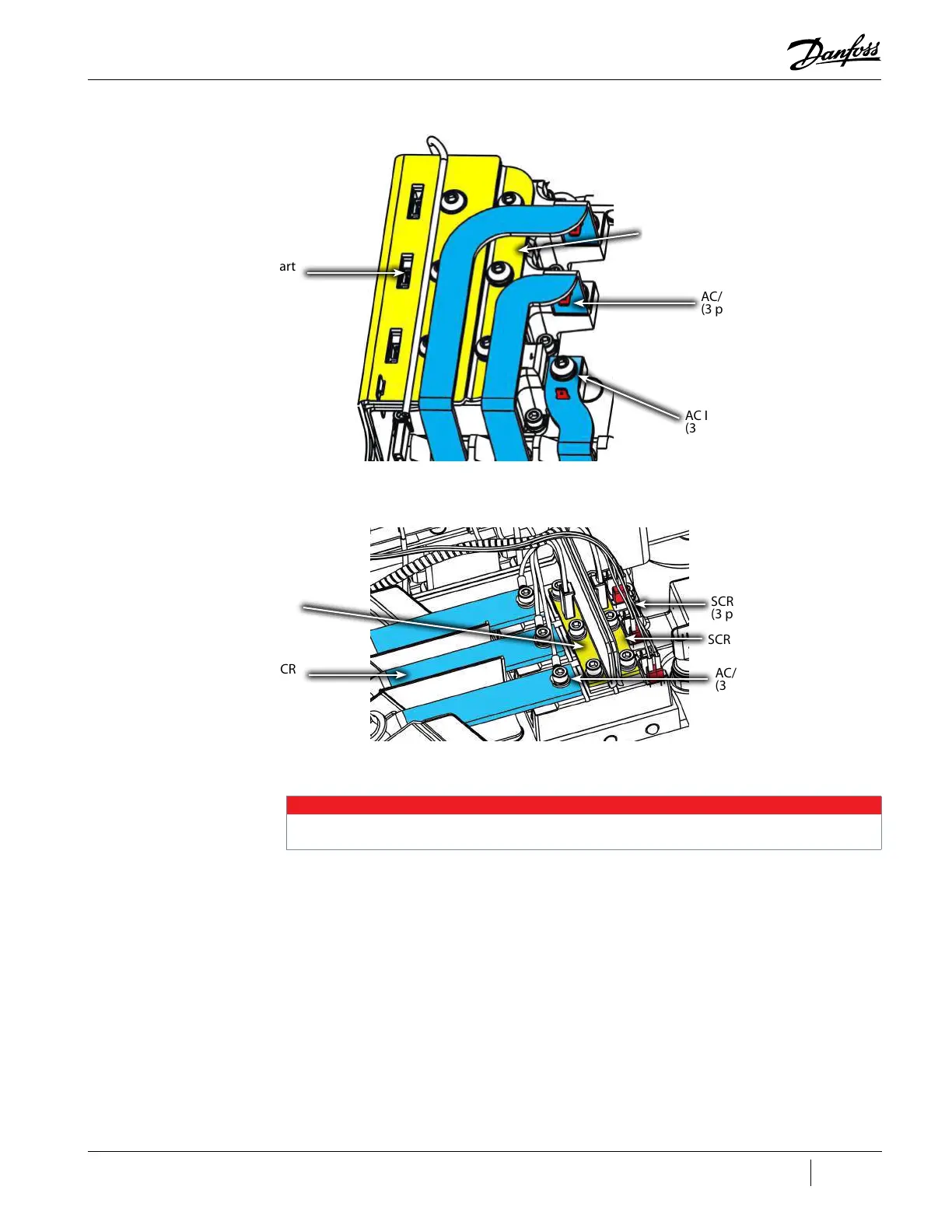
Figure 4-144 SCR Connections - TTS/TGS/TTH/TGH Rev. F and Earlier (Except TTS300/TGS230)
Figure 4-145 SCR Connections - TTS/TGS/TTH/TGH Rev. H (Except TTS300/TGS230)
4.19.2 SCR Verification
4.19.2.1 Diodes Verification - Two Hole Mount
1. Isolate compressor power as described in Section "1.8 Electrical Isolation" on page 19.
2. Remove the DC Bus Bars from the SCRs. Refer to "4.22.3 DC Capacitor Bus Bar Assembly
Removal and Installation" on page 158.
3. Using a multimeter set for diode measurements, place the black (-) lead on terminal 1 of the
SCR and place the red (+) lead on terminal 3. The measured value should be between 0.3V and
0.45V. Refer to "Figure 4-146 SCR Terminals - Two Hole Mount" on page 136 and "Figure 4-147
SCR Terminals - Four Hole Mount" on page 136 for terminal locations.
4. Perform this test for each SCR.
5. Install the DC Bus Bars to the SCRs. Refer to "4.22.3 DC Capacitor Bus Bar Assembly Removal
and Installation" on page 158.
6. Install the top covers. Refer to "4.2 Compressor Covers" on page 56.
7. Return the compressor to normal operation.
AC Input to SCR
(3 places)
SCR to DC Bus
(+ and -)
SCR Gate Cables to Soft Start
(3 places)
AC/DC Harness Connector
(3 places)
AC Input to SCR
(3 places)
SCR to DC Bus ( -)
SCR Gate Cables to Soft Start
(3 places)
AC/DC Harness Connector
(3 places)
SCR to DC Bus (+)
NOTE
A faulty SCR module can cause the DC bus and Mains Input current to be imbalanced. This can stress the Inverter and Stator. If an
SCR module is found to be faulty, then the Inverter and Stator must also be verified.

 Loading...


