132 of 282 M-SV-001-EN Rev. G
b. For compressors with the Open-Top Soft Start, install connectors J1 and J8. Refer to
"Figure 4-136 Open-Top Soft Start J1 and J8 Removal" on page 129.
3. Install the DC-DC connections.
a. If the DC-DC is the potted style, install connectors J1 and J4. Refer to "Figure 4-134 DC-DC
Connectors (Potted)" on page 128.
b. If the DC-DC is the open-frame style, only J1 will need to be installed. Refer to "Figure
4-133 DC-DC Connectors (Open Frame)" on page 127.
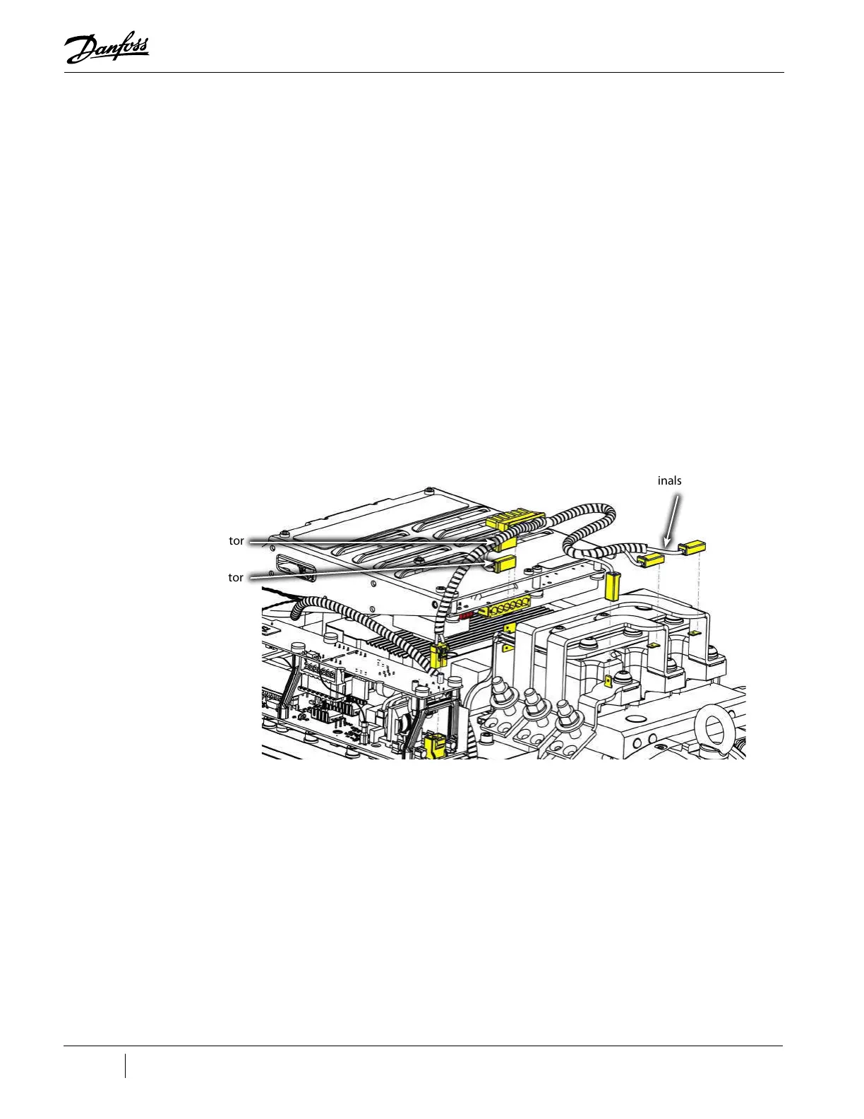
4. Install the -DC and +DC spade terminals onto the DC bus bar.
a. For Revision F and earlier compressors refer to "Figure 4-140 AC Input and Spade
Connector Installation - TTS/TGS/TTH/TGH Rev. F and Earlier (Except TTS300/TGS230)".
b. For Rev H compressors, refer to "Figure 4-141 AC Input and Spade Connector Installation -
TTS/TGS/TTH/TGH Rev. H (Except TTS300/TGS230)" on page 133.
5. Install the L1, L2, and L3 terminals from the AC Bus Bars.
a. For Revision F and earlier compressors, refer to "Figure 4-140 AC Input and Spade
Connector Installation - TTS/TGS/TTH/TGH Rev. F and Earlier (Except TTS300/TGS230)".
b. For Rev H compressors, refer to "Figure 4-141 AC Input and Spade Connector Installation -
TTS/TGS/TTH/TGH Rev. H (Except TTS300/TGS230)" on page 133.
Figure 4-140 AC Input and Spade Connector Installation - TTS/TGS/TTH/TGH Rev. F and Earlier (Except TTS300/TGS230)
-DC Spade Connector
+DC Spade Connector
AC/DC Bus Bar (L1, L2, & L3)
Spade Terminals
(3 places)

 Loading...


