217 of 282
M-SV-001-EN Rev. G
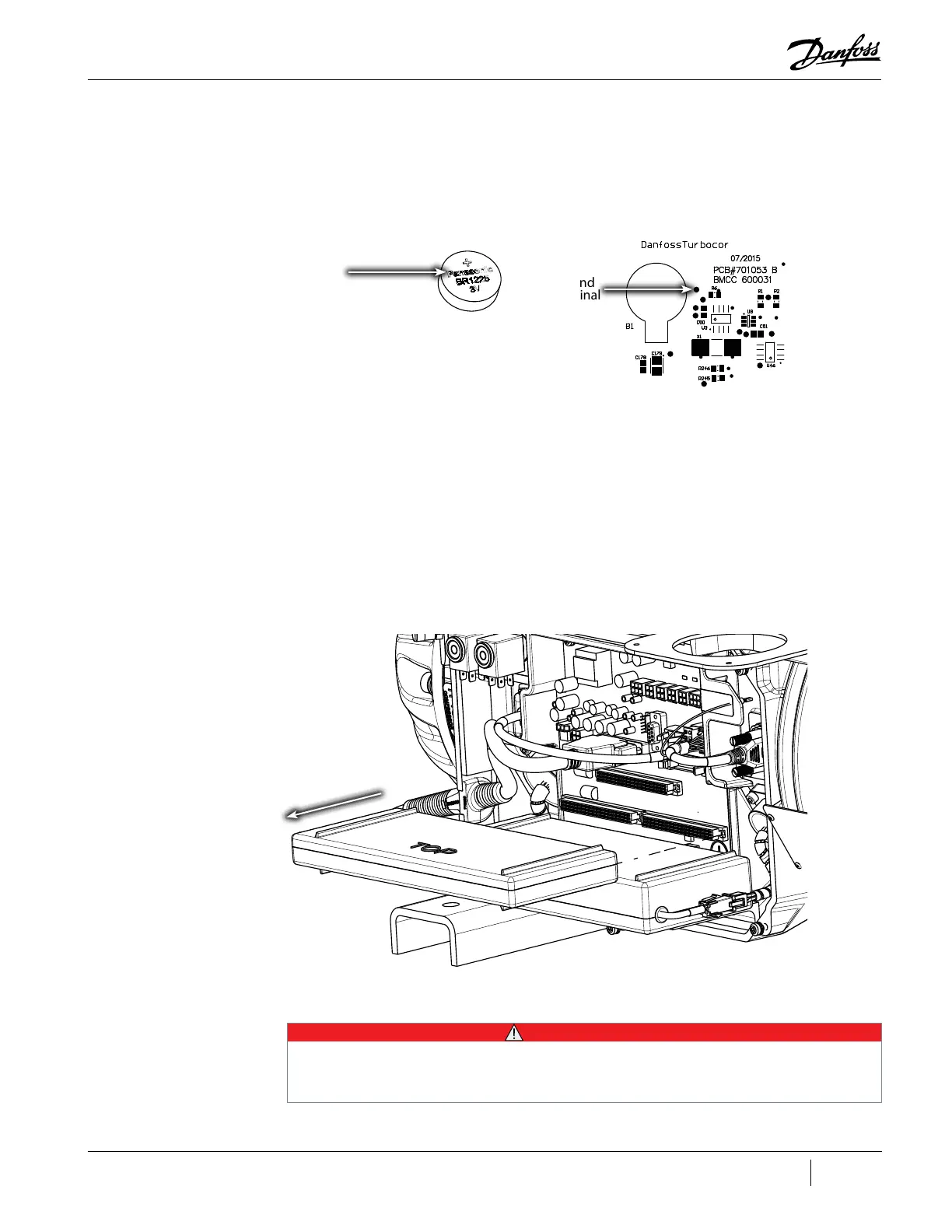
3. Set the multimeter for voltage measurements and place the red (+) probe on the battery itself
(top)and the black (-) probe on the ground terminal shown below.
• The measurement should be between 2.85V and 3.15V
Figure 4-275 BMCC Battery Measurement
4.28.4 BMCC Removal and Installation
4.28.4.1 BMCC Removal
1. Isolate compressor power.
2. Remove the Service Side Cover. Refer to "4.2.3.1 Service Side Cover Removal and Installation"
on page 58.
3. Verify the LEDs on the Backplane have turned off.
4. Carefully disconnect the Serial Driver from the Backplane and slide it slowly away from the
compressor. Refer to "4.27.4 Serial Driver Removal and Installation" on page 213.
5. Carefully disconnect the BMCC from the Backplane and slide it slowly away from the
compressor. Refer to "Figure 4-276 BMCC Removal".
Figure 4-276 BMCC Removal
4.28.4.2 BMCC Installation
Ground
Terminal
Top side (+)
• • • CAUTION • • •
When replacing the BMCC, a bearing calibration must be performed and saved to electrically erasable programmable read-only
memory (EEPROM). This may need to be done up to three times. The BMCC will then use the new values stored in EEPROM to
operate the compressor. Using default calibration data from a newly installed BMCC to operate a compressor could cause erratic
behavior.

 Loading...


