181 of 282
M-SV-001-EN Rev. G
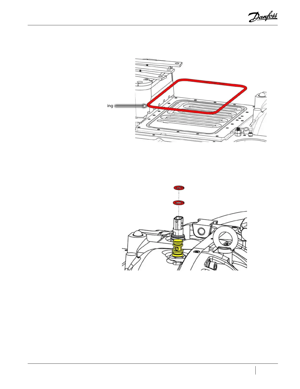
16. Remove and discard the large Inverter O-ring from the compressor housing. Refer to "Figure
4-226 Inverter O-ring Removal - TTS/TGS/TTH/TGH (Except TTS300/TGS230)").
Figure 4-226 Inverter O-ring Removal - TTS/TGS/TTH/TGH (Except TTS300/TGS230)
17. Carefully remove the two (2) O-rings from the SCR Manifold Return Brass Fitting. Use caution to
not damage the surface of the fitting. Refer to "Figure 4-227 SCR Manifold Return Brass Fitting
Removal - TTS/TGS/TTH/TGH (Except TTS300/TGS230)".
Figure 4-227 SCR Manifold Return Brass Fitting Removal - TTS/TGS/TTH/TGH (Except TTS300/TGS230)
4.23.6.3 Specific Inverter Installation Steps - TTS300/TGS230
1. Clean O-ring groove in the main compressor housing.
2. Apply O-Lube to the Inverter O-ring and place the O-ring in the compressor housing groove.
3. Apply O-Lube to the O-rings and install them into the SCR cooling manifold. Refer to "Figure
4-228 SCR Cooling Plate O-ring Installation - TTS300/TGS230" on page 182.
O-ring

 Loading...


