202 of 282 M-SV-001-EN Rev. G
4.25.2.3 Input Resistance Measurement
1. Isolate the compressor power as described in Section "1.8 Electrical Isolation" on page 19.
2. Unplug all connectors to the DC-DC Converter.
3. Using a multimeter set for resistance measurements, place the multimeter leads in the J1, HV
DC input plug terminals. Refer to "Figure 4-258 Potted DC-DC" on page 204 and "Figure 4-259
Open Frame DC-DC" on page 204. The result should not be 0.0Ω. The result can be open or
>150kΩ.
4. Reverse the multimeter leads on the J1 plug terminals. The result should not be 0.0Ω. The
result can be open or >150kΩ.
5. Place the multimeter leads in J4, 15VAC input terminals. The result should be >1MΩ.
6. Reverse the multimeter leads on the J4 terminals. The result should be >1MΩ.
4.25.2.4 Output Resistance Measurement
1. Isolate the compressor power as described in Section "1.8 Electrical Isolation" on page 19.
2. Unplug all connectors to the DC-DC Converter.
3. Using a multimeter set for resistance measurements, place the multimeter leads on the J2,
250VDC output terminals. Refer to "Figure 4-258 Potted DC-DC" on page 204 and "Figure
4-259 Open Frame DC-DC" on page 204. The result should be a rising or falling value, not zero
or infinity.
4. Reverse the multimeter leads on the J2 (250VDC output ) terminals. The result should be a
rising or falling value, not zero or infinity.
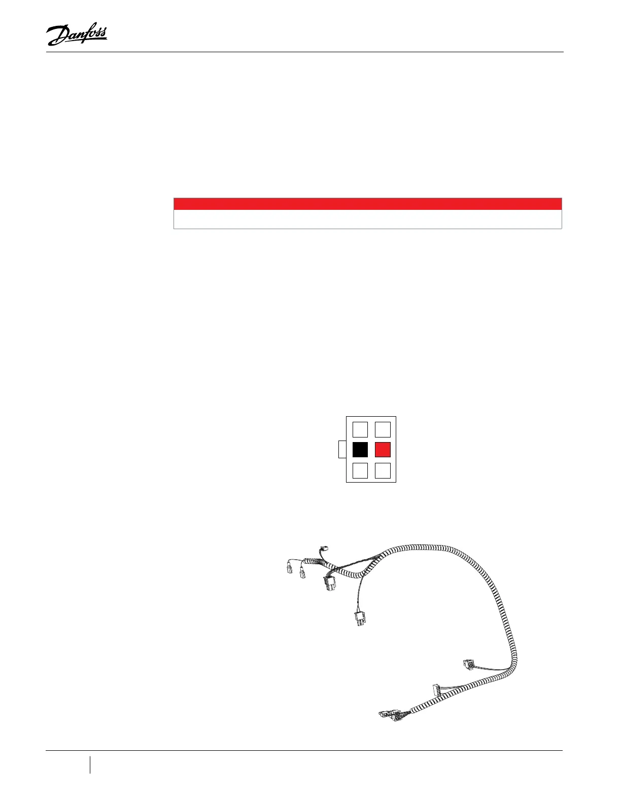
5. Place the multimeter leads in the middle row of the J3, 24VDC output terminals for the potted
DC-DC Converter or J4 for the open frame DC-DC Converter. Refer to "Figure 4-255 J3 - 24VDC
Output Connector". The result should be a rising or falling value, not zero or infinity.
Figure 4-255 J3 - 24VDC Output Connector
6. Reverse the multimeter leads on the J3 (24VDC output ) terminals and measure the resistance.
The result should be a rising or falling value, not zero or infinity.
4.25.3 DC-DC Supply Cable Harness
Figure 4-256 DC-DC Harness
NOTE
J4 (15VAC) is only for the Potted DC-DC Converter.
To J22 on Backplane
To Motor Thermistor
Terminals
To J4 on Backplane
To J2 on
DC-DC
To J24 on Backplane
To J9/J7 on Soft Start
To J20 on Backplane
To J3 on potted
DC-DC/J4 on open
frame DC-DC

 Loading...


