26 of 282 M-SV-001-EN Rev. G
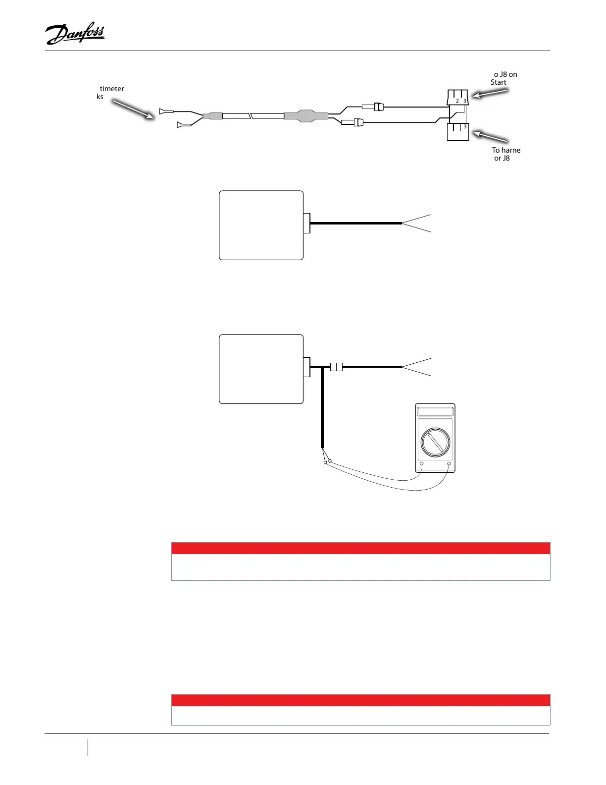
Figure 1-18 Connect DC Bus Test Harness (Open-Top Soft Start)
Figure 1-19 DC Bus Test Harness Connection Diagram (Open-Top Soft Start)
4. Route the cables through the cable passage beside the DC-DC Converter, down into the
service side. Refer to "Figure 1-16 Cable Passage" on page 24.
NOTE
When checks are complete, disconnect and remove the test harness. If the main housing has two cable passages, wither passage
can be used.
5. Reinstall the Top Cover and Mains Input Cover. Refer to "4.2 Compressor Covers" on page 56.
6. Reapply AC power to the Compressor.
7. Insert the positive voltmeter lead into the DC (+) test harness lead, and the negative voltmeter
lead into the DC (-) test harness lead. Refer to "Table 1-3 Expected DC Bus Voltage" on page
25 for the expected DC bus voltage. If the DC bus voltage is not present, or if it is outside the
“Expected DC Bus Voltage” range shown in "Table 1-3 Expected DC Bus Voltage" on page 25,
verify proper incoming AC input, verify SCR Gates, and verify SCR Diodes. If incoming AC power
is correct, and the SCRs pass the diode and gate tests, replace the Soft Start.
NOTE
There are no replaceable fuses present in the Open-Top Soft Start.
1 2 3
1 2 3
To J8 on Soft
Start
To harness
for J8
Multimeter
jacks
ORIGINAL CONNECTIONS
Soft Start
(Top Side)
Harness to DC Link
J8
CONNECTIONS WITH DC BUS TEST HARNESS
Soft Start
(Top Side)
Harness to DC Link
J8
00.0
Volt
Meter

 Loading...


