M3-14 031914
Scale Cabinet:
8. The KM3 Contactor sends the 3-phase AC
supply voltage to the GS2 Power Supply.
(Illustration 24) The KM3 Contactor is
energized by the 30 wire coming from the
AR7 Safety Output. (Illustration 22) After all
guards are closed and “Master Off” buttons
are pulled out and the machine has moved to
the “Run” position, the AR7 Output energizes
and sends 24 VDC on wire 30 to energize the
KM3 Contactor.
9. The GS2 Power Supply creates 24 VDC
throughout the QF7 Breaker to the AR16
Power Supply Module in the Scale Cabinet.
(Illustration 24) The common wire 302 is sent
directly to the Power Supply Module. The 24
VDC is sent on wire 303 in series throughout
the Stepper Drive Modules.
10. The QF6 Breaker sends 24 VDC Motor
Power supply voltage to the M16 Classifier
Conveyor.
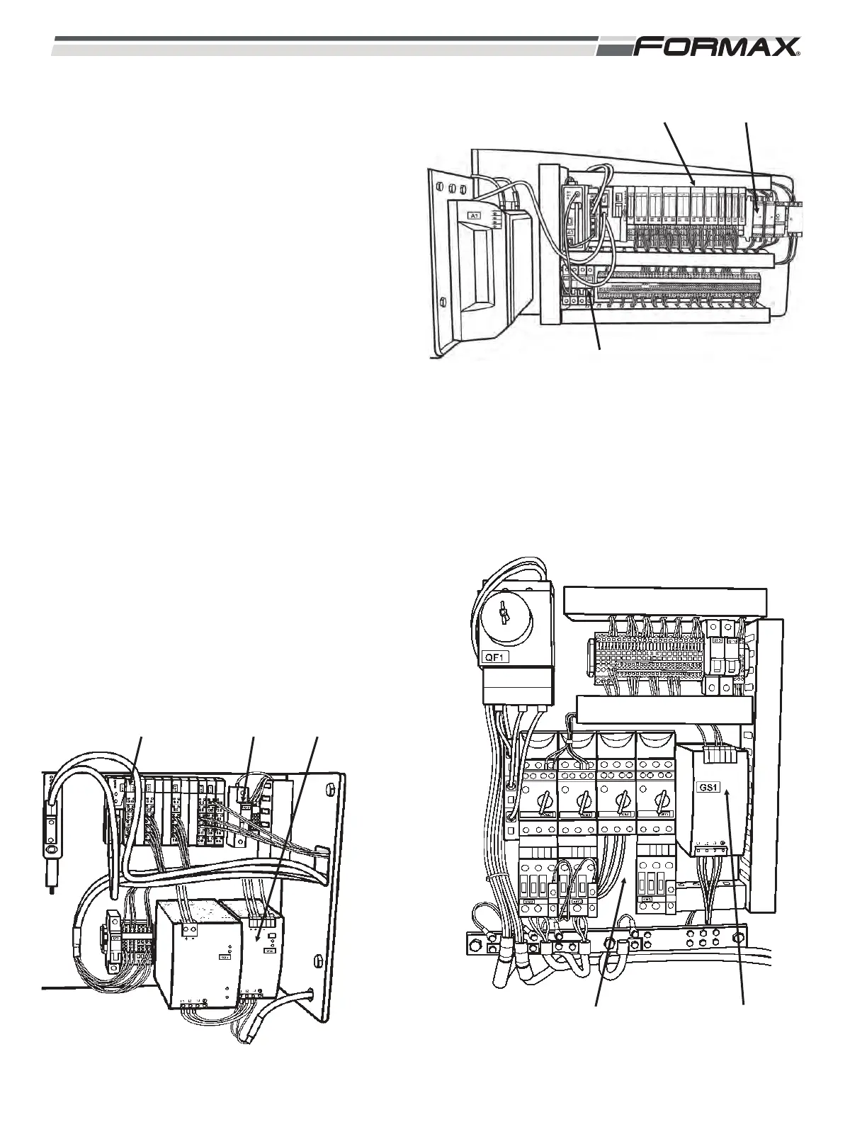
11. 24 VDC supply voltage is sent to the Control
Units inside of the Linear and Rotary Actuator
Motors. This voltage is sent by the GS1
Power Supply through the QF6 Breaker on
wire “83.” (Illustration 22 and 23)
QF7
ILLUSTRATION 24
GS2AR16
ILLUSTRATION 23
GS1 POWER
SUPPLY
KM4
CONTACTOR
ILLUSTRATION 22
KA1/KA2
QF6
AR7
 Loading...