031914 M3-41
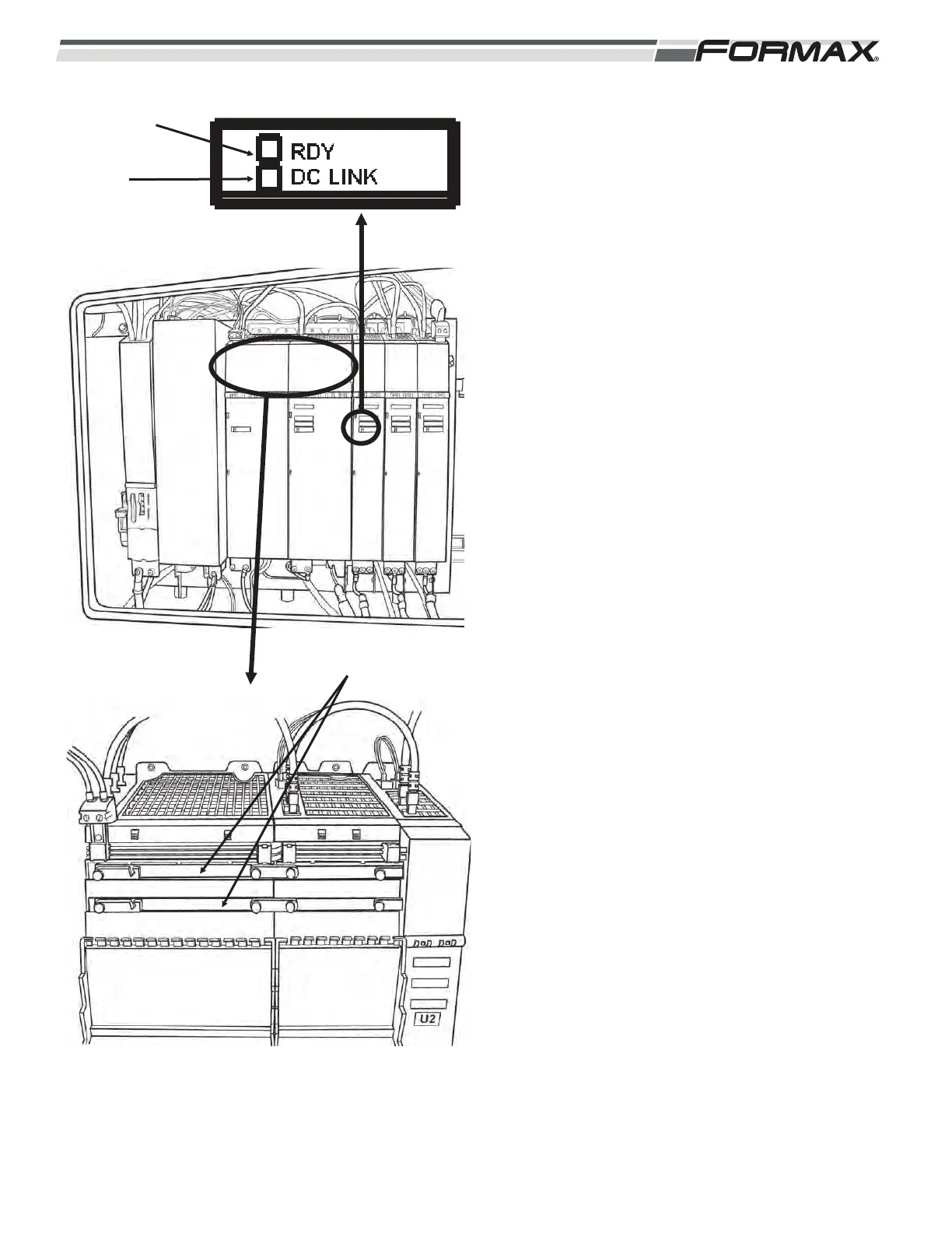
DC Bus Bars: The “U3” Active Line Module takes a
3-phase AC supply voltage and rectifies (converts)
it to approximately 650 VDC. (Illustration 61) The
650 VDC is sent through the Bus Bars to the Servo
Drives for use in running the Servo Motors.
Status Indicator LED’s: There are Status LED’s
on the Servo Drive Modules that indicate the status
of the operating system. The LED’s can illuminate
“green,” “orange,” “red” or “off.” (Illustration 61)
RDY LED: The “Ready” LED shows the
status of the Servo Drive Module.
LED OFF: Indicates that there is no 24
VDC Control Voltage. Check the 24
VDC at the X24 Terminal Plug.
Green LED: Indicates that there are no
faults or problems with the Servo Drive
Module and it is ready to run.
Orange LED: The machine is booting
up and communication is being
established. If the machine is already
booted up then there is a problem in the
communication between the appropriate
Motion Control Module and the Servo
Drive Module.
Red LED: Indicates that there is a
“Fault” present in the Servo Drive.
LED Flashing Green and Red: The
Motion Control Module is downloading
firmware information to the Servo Drive.
This will only happen after a new Servo
Drive has been installed.
LED Flashing Green/Orange: The
Motion Control Computer has
recognized the Servo Drive.
LED Flashing Red/Orange: There is a
“Fault” present, but the Motion Control
Computer has recognized the Servo
Drive.
ILLUSTRATION 61
DC BUS BARS
READY LED
DC LINK
LED
 Loading...