M4-6 031914
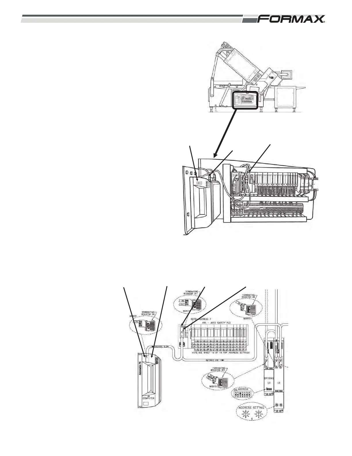
A1 Computer Assembly: The Computer sends
Control Output Signals and receives Input Signals
from the Slicer Components over the Profibus
Network. The Profibus Communication is
processed through the Profibus Interface Board.
(Illustration 7 and 8) The Profibus Network requires
a Terminating Resistor to be installed at the start of
the network and at the end of the network. The
Profibus Cable plugged into the Profibus Interface
Board must have the Terminating Resistor Switch
turned to the “On” position. The Profibus Network
Cable then travels to the AR1 Safety Computer.
AR1 Safety Computer: The Main Profibus Cable
travels from the A1 Computer to the AR1 Safety
Computer and then out to the U1 Motion Control
Module. (Illustration 7 and 8) The AR1 Safety
Computer monitors the status of the “Master Off”
buttons, the “Safeties,” the “Operational Inputs” and
controls the “Operational Outputs” for the “Control
Relays” and “Motor Contactors.” The Safety
“Status” is sent to the Computer and U11 Motion
Control Module over the Profibus Network. When a
Safety Condition occurs, the operational functions
of the Slicer will be inhibited.
ILLUSTRATION 7
A1 COMPUTER
ASSEMBLY
PROFIBUS
NETWORK
CABLES
AR1 SAFETY
COMPUTER
ILLUSTRATION 8
TERMINATING
RESISTOR “OFF”
TERMINATING
RESISTOR “OFF”
A1
COMPUTER
AR1 SAFETY
COMPUTER