031914 M4-7
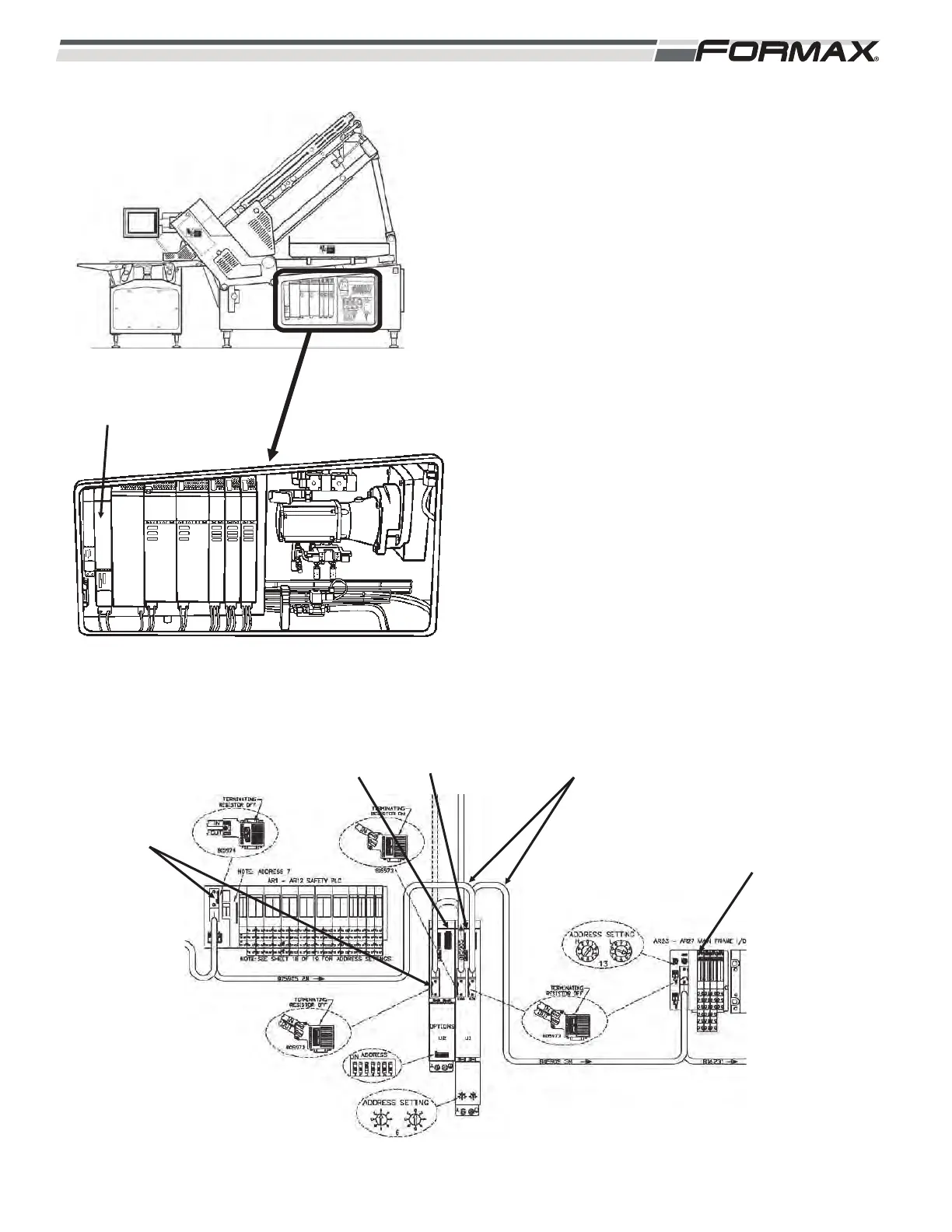
U1 Motion Control Module: The Main Profibus Cable
travels from the AR1 Safety Computer to the U1 Motion
Control Module and then out to the AR23 Main Frame
I/O Node. (Illustration 9 and 10) The Terminating
Resistors at U1 and A8 should be set to “off.” The U1
Motion Control Module uses a second Profibus Network
Cable to communicate with the U2 and U9 Motion
Control Modules. This Cable starts at the X126
Connector on the U1 Motion Control Module (terminating
resistor set to “On”) and runs in series to the U2 and U9
Motion Control Modules. The Terminating Resistor on
the U9 Plug should also be set to the “On” position. The
U1, U2 and U9 Motion Controllers communicate with all
of the Servo Drives and Servo Motors using an Ethernet
Network running between all of the components of the
Servo System. (Refer to the Motion Control/Servo Drive
section for more information on the Motion Control/Servo
Drive Ethernet Network.)
AR23 Main Frame I/O Node: The Main Profibus Cable
travels from the U1 Motion Control Module to the AR23
Main Frame Node and then out to the XS3 Main Frame
Manifold. The AR23 Main Frame Node receives input
signals from the SQ35 Loaf Load Switch and the SP1
Pressure Switch. The AR23 Node also sends output
signals to operate the EL1 Status Light and the SQ35
Loaf Load Status LEDs.
ILLUSTRATION 9
U1 MOTION
CONTROLLER
ILLUSTRATION 10
TERMINATING
RESISTOR
SWITCH SET
TO “ON”
U2 MOTION
CONTROLLER
PROFIBUS
CABLES
AR23 MAIN
FRAME NODE
U1 MOTION
CONTROLLER