M4-20 031914
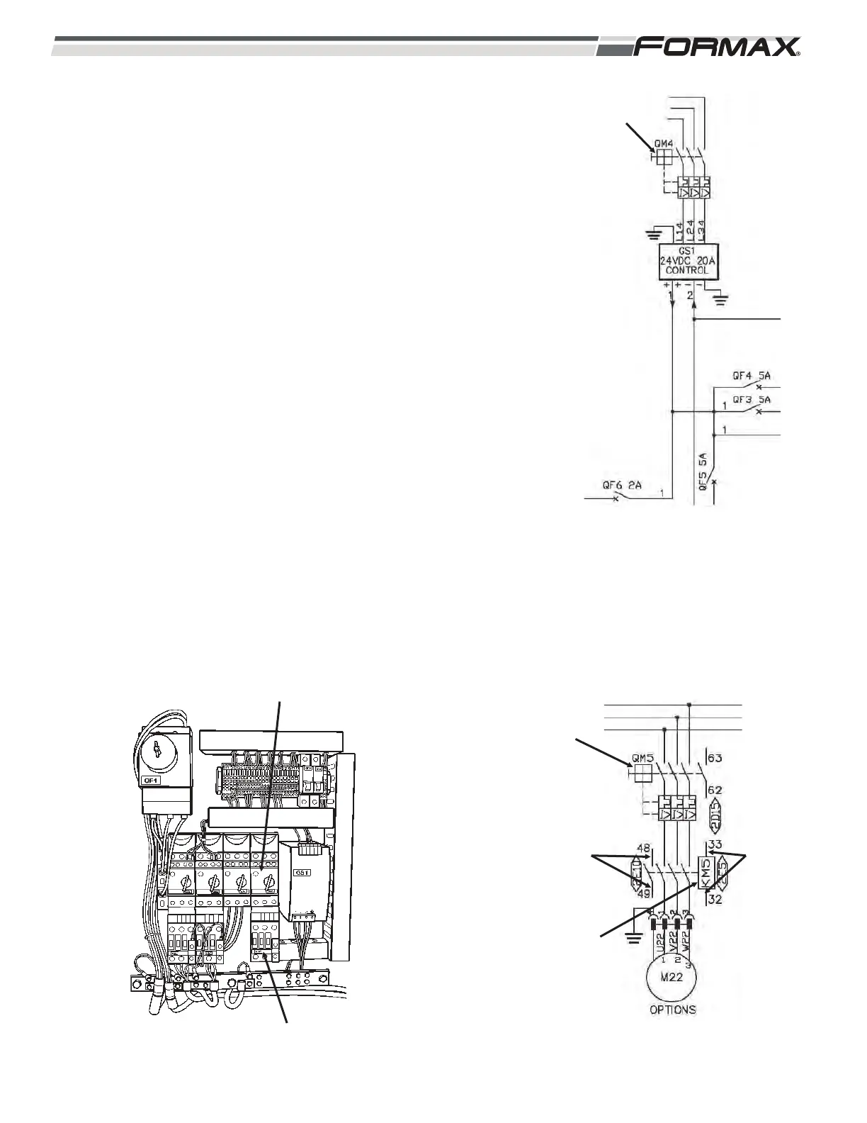
6. QM4 Circuit Controller: The QM4 Circuit Controller provides the
thermal overload protection for the AC supply voltage going to the
GS1 24 VDC Power Supply. (Illustration 39) When switched to the
“Off” position, the GS1 Supply Voltage is disabled. When in the “On”
position, QM4 supplies 3-phase AC Supply Voltage to the Power
Supply.
7. QM5 Circuit Controller/KM5 Contactor:
QM5 Circuit Controller: The QM5 Circuit Controller provides the
thermal overload protection for the AC supply voltage going to the
optional KM5 Optional Contactor. When switched to the “Off” position,
the Power Voltage going to the KM5 Option is disabled. When in the
“On” position, it supplies 220 VAC to the KM5 Knife Heater Contactor.
When QM5 is turned “on,” wires 48 and 49 transfer a 24 VDC signal
from the AR11 Input Module, through the N.O. contacts on QM5
Circuit Controller and back to the AR11 Input Module to tell the
Computer that the QM5 Circuit Controller is “on.”
(Illustration 40 and 41)
KM5 Contactor: When energized, the KM5 Contactor sends 3-phase
AC supply voltage to the optional component. (Illustration 40 and 41)
When all of the Guards are closed and all “Safety Conditions” are met,
the KA1/KA2 Relay energizes and the Computer sends the 24 VDC
and common from the AR9 Output Module on wires 32 and 33 to
energize the coil of the KM5 Contactor and sends the voltage to the
optional component. When the KM5 Contactor energizes, wires 48
and 49 transfer a 24 VDC signal from the AR9 Input Module, through
the N.O. contacts on KM5 Contactor and back to the AR9 Input
Module to tell the Computer that the KM5 Contactor is energized.
ILLUSTRATION 39
QM4 CIRCUIT
CONTROLLER
ILLUSTRATION 40
TO AR12
INPUT
MODULE
TO AR12
INPUT
MODULE
QM5 CIRCUIT
CONTROLLER
KM5
CONTACTOR
ILLUSTRATION 41
QM5
KM5 CONTACTORS
 Loading...