M4-22 031914
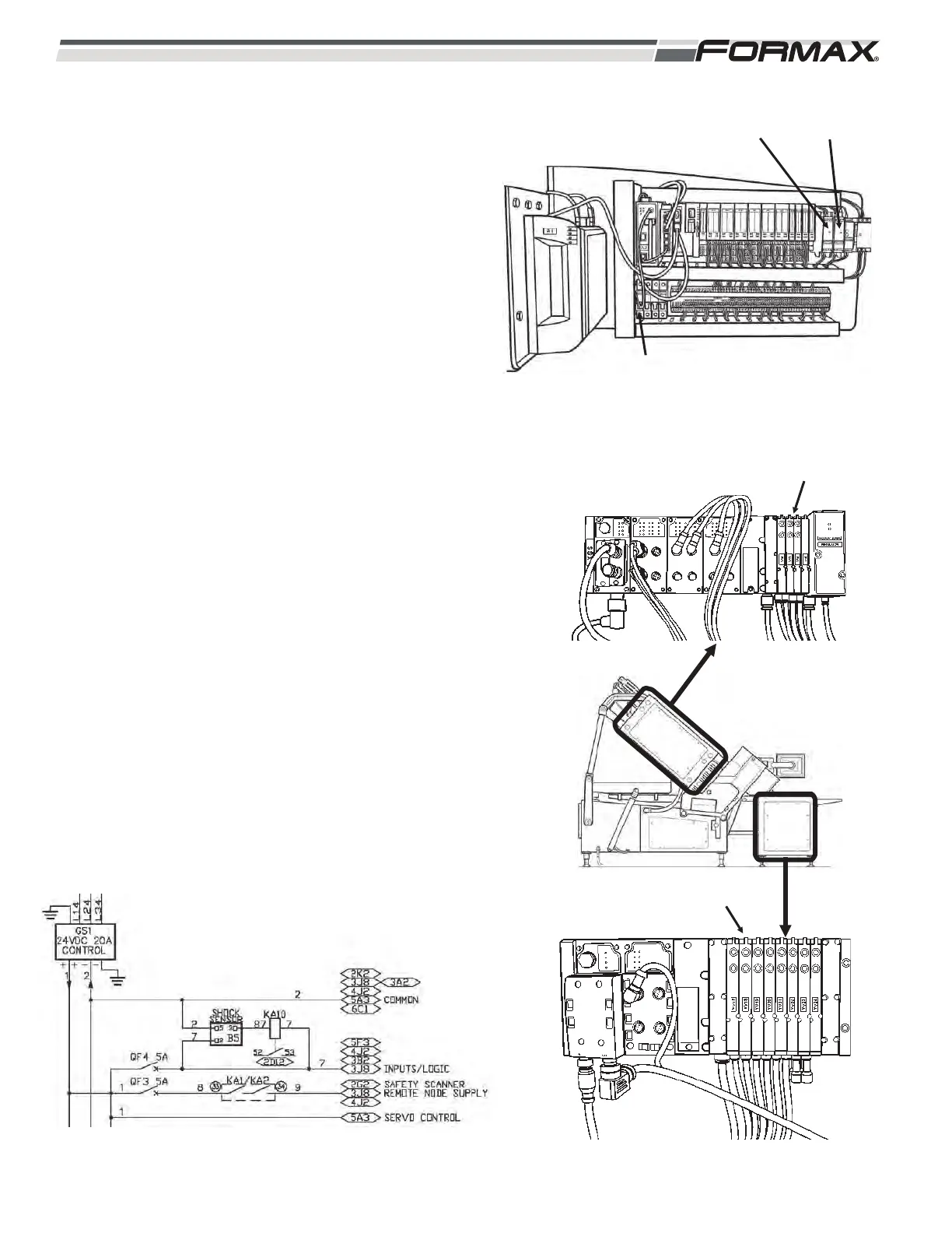
4. The QF3 Breaker transfers 24 VDC on wire “8” to
the KA1/KA2 Relay. (Illustration 46)
a. When the Slicer is in the “Ready” position and
all guards are closed and all “Master Off”
buttons are pulled out, the KA1/KA2 Relay
energizes. The KA1/KA2 Relay sends 24 VDC
on wire “9” as a Supply Voltage to operate all
of the Remote Nodes. (Illustration 47) If a
guard is opened or a “Master Off” button is
pressed, the KA1/KA2 Relay de-energizes and
there will be no voltage to operate the Remote
Nodes.
b. When the Slicer is in the “Ready” position and
all guards are closed and all “Master Off”
buttons are pulled out, the KA1/KA2 Relay and
KA3/KA4 Relays energize. (Illustration 48) The
KA1/KA2 Relay sends 24 VDC to the Safe Off
Relays on all the servo Drives except the U7
Drive. This allows all of the Servo Motors
controlled by these Drives to operate. The
KA3/KA4 Relay sends 24 VDC to the U7 Servo
Drive to operate the M6 Infeed Structure Motor.
c. When the “Move To Clean” button is pressed,
the KA1/KA2 Relay de-energizes and disables
the Remote Nodes. The KA3/KA4 Relay
remains energized to allow the Infeed Structure
Motor M6 to operate to lower the structure to
the clean postion. After moving to the “Clean”
position, the KA3/KA4 Relay de-energizes and
disables the U7 Servo Drives.
XS4 REMOTE NO`DE
ILLUSTRATION 47
ILLUSTRATION 48
ILLUSTRATION 46
KA1/KA2
KA3/KA4
QF3 CIRCUIT BREAKER
XS5 REMOTE NODE
 Loading...