031914 M4-47
REMOTE INPUT/OUTPUT NODES
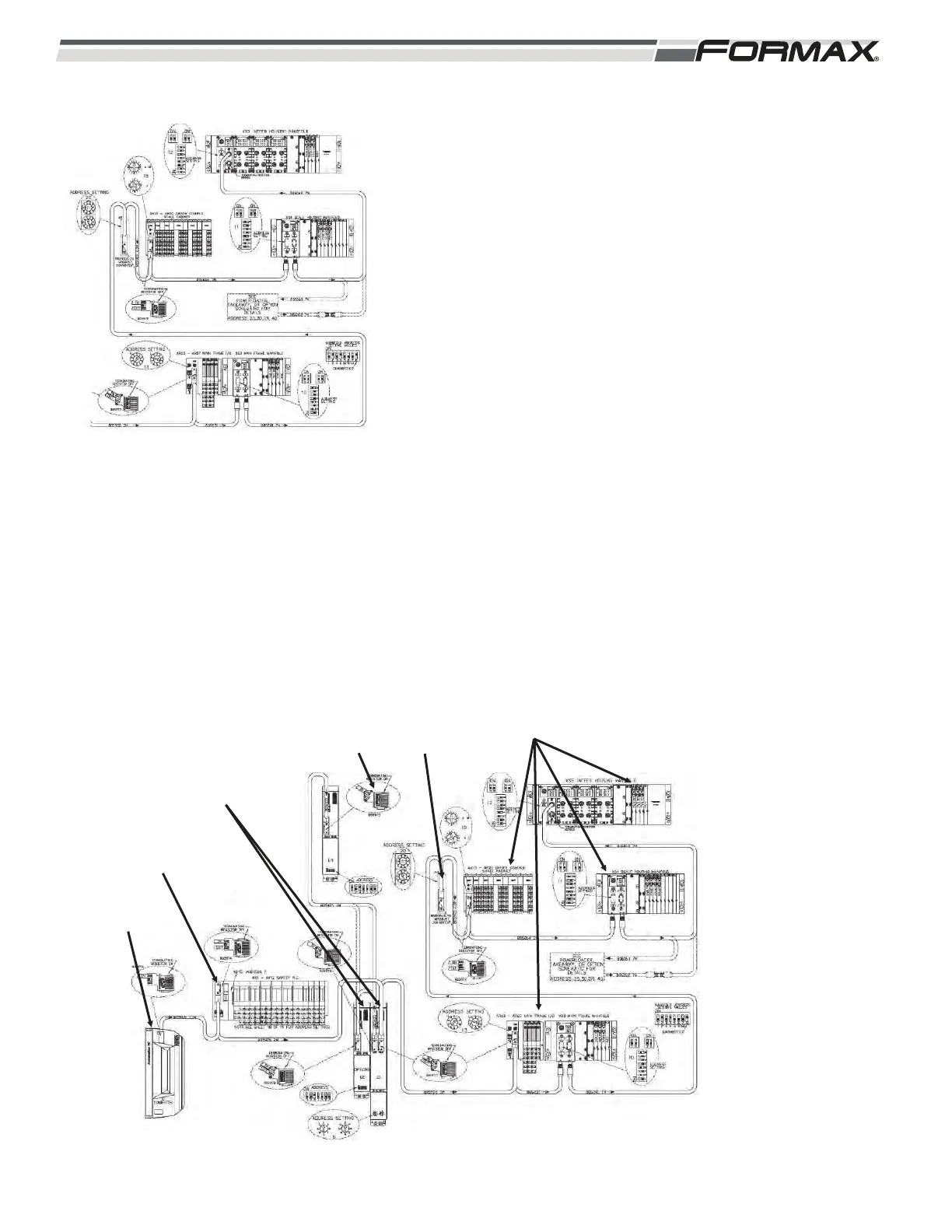
The Profibus Network Cables run in series to the Safety Computer,
the U1 Motion Control Module, all of the Remote Input/Output
Nodes and the A8 Modbus Converter. (Illustration 117) The
Computer sends Control Signals to the Remote Nodes over the
Profibus to operate the machine components. The “Remote Nodes”
send “status” and “position” information through the Profibus
Cables to the Computer. The Computer sends “command” signals
through the Profibus Cables to the “Remote Nodes” to control the
operation of the machine components.
1. The XS5 Infeed Housing Manifold Node is that last Node in
the Profibus Network and should have a Terminating
Resistor installed in the “Out” Port. (Illustration ) All of the
rest of the Manifold Nodes should not have a Terminating
Resistor. The Nodes with a Terminating Resistor built into
the Profibus Cable should be set to the “Off” position.
(Illustration 116)
2. Each Remote Node has an “address setting” that must be
set correctly for the Profibus communication with that Node
to operate. (Illustration 116) Refer to the “Profibus Routing
and Address Information” page of the schematic for the
correct address for each Node.
IMPORTANT!
When replacing any of the “Remote Input/Output Nodes,” you
must set the address dials to the correct setting.
ILLUSTRATION 116
ILLUSTRATION 117
REMOTE NODES
SAFETY
COMPUTER
COMPUTER
A8 MODBUS
CONVERTER
MOTION CONTROL
MODULES
PROFIBUS
NETWORKING
TERMINATING
RESISTOR