M4-48 031914
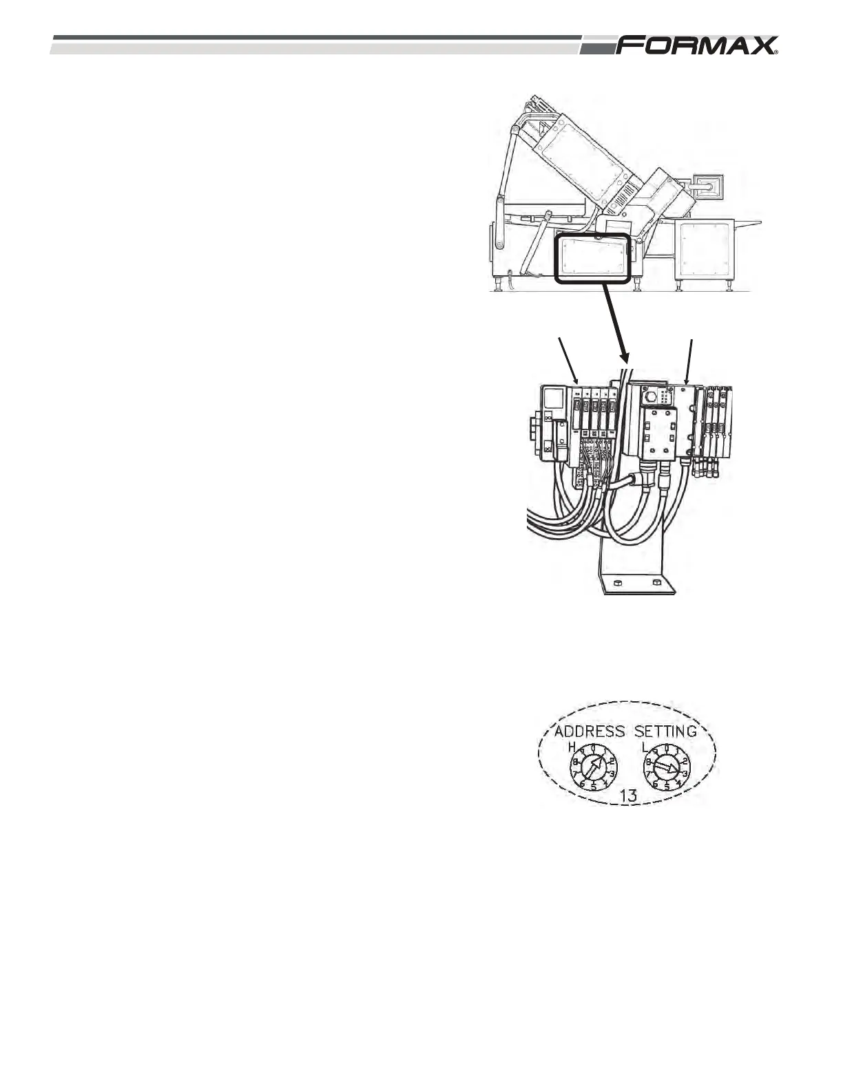
AR23 MAIN FRAME I/0 NODE: The Main Profibus
Cable travels from the U1 Motion Control Module to
the AR23 Main Frame I/O Node and then out to the
XS3 Main Frame Manifold. (Illustration 118) The AR23
Main Frame I/O Node receives “Input” signals from the
SQ19 Loaf Lift Saddle Switch and SP1 Pressure
Switch. The AR23 I/O Node also sends “Output”
signals to operate the LEDs in the Loaf Lift Saddle
Switch, The Status Lights and the HA1 Horn.
1. The GS1 Power Supply sends 24 VDC Control
Voltage through the QF4 Circuit Breaker on
wires 7 and common (2) to terminals “U-SYS”
and “GND-SYS” on the AR23 I/O Node
located in the Main Cabinet. This voltage is
used to operate the components controlled by
the AR23 I/O Node.
2. The Terminating Resistor on the Profibus Plug
should be set to the “Off” position.
3. The Address Setting for the AR23 Node must
be set correctly in order for the Node to
operate. (Illustration 119)
IMPORTANT!
When replacing any of the Remote Nodes, the
“address setting” must be set correctly or the
Remote Node will not operate correctly! There will
be “NO” Profibus Communication between the
Computer and the Node. Refer to the “Profibus
Routing and Address Information” page of the
schematic for the correct address for each Node.
ILLUSTRATION 119
ILLUSTRATION 118
XS3 MAIN FRAME
MANIFOLD
AR23 MAIN
FRAME NODE