031914 M4-59
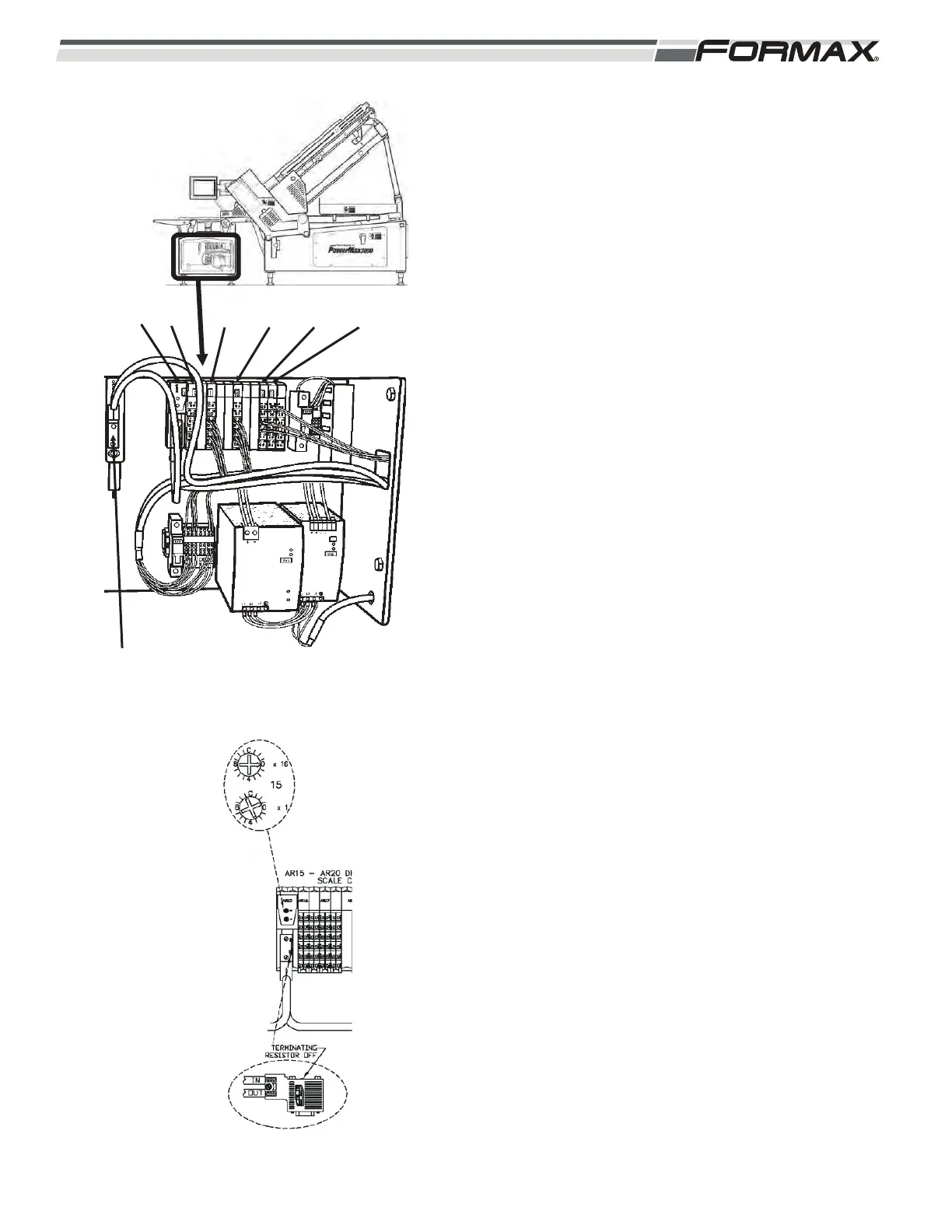
AR15 SCALE DRIVER CONTROL NODE: The Main
Profibus Cable travels from the A8 Modbus Converter
to the AR15 Scale Driver Control Node and then out to
the XS4 Scale Housing Manifold. (Illustration 134) The
AR15 Driver Control Node Sends the “Control Signals”
to the AR17, AR18 and AR19 Stepper Modules that
operate the Dynamic Scale Conveyor Motors. The
AR15 Node also sends the control voltages to run the
M16 Classifier Rotary Actuator Motor.
1. When all “Safety” conditions have been met,
KA1/KA2 Relay sends 24 VDC on wires 30 and
31 (common) to energize the KM3 Contactor.
The KM3 Contactor sends 3-phase AC Supply
voltage to the GS2 24 VDC Power Supply
located in the Scale Cabinet. The GS2 Power
Supply rectifies the 3 phase 460 VAC to 24
VDC. 24 VDC is sent on wire “301” to the QF7
Circuit Breaker.
2. THE QF7 Circuit Breaker sends the 24 VDC
Control Voltage on wires 303 and common
(302) to terminals “24” and “26” on the AR16
Power Module located in the Scale Cabinet.
This voltage is sent from terminal “25” on the
AR16 Power Module to the AR17, AR18 and
AR19 Stepper Modules as a Supply Voltage to
operate the Dynamic Scale Conveyor Motors.
3. The Terminating Resistor on the Profibus Plug
should be set to the “Off” position.
4. The Address Setting for the AR15 Node must
be set correctly in order for the Node to operate.
(Illustration 135)
IMPORTANT!
When replacing any of the Remote Nodes, the
“address setting” must be set correctly or the
Remote Node will not operate correctly! There will
be “NO” Profibus Communication between the
Computer and the Node. Refer to the “Profibus
Routing and Address Information” page of the
schematic for the correct address for each Node.
A8 MODBUS CONVERTER
ILLUSTRATION 134
AR15 AR16
ILLUSTRATION 135
AR17 AR18 AR19 AR20