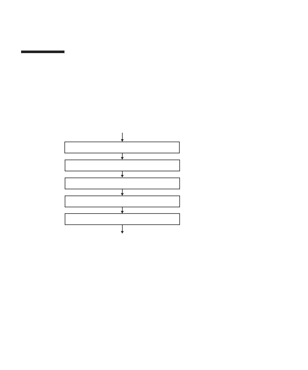
1. Enable removal of PSU backplane unit
3. Remove operation panel
4. Install operation panel
5. Install PSU backplane unit
(Restore chassis requiring maintenance)
(Remove chassis requiring maintenance)
2. Remove PSU backplane unit
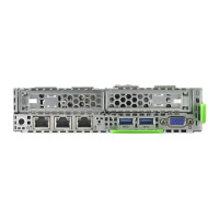
■
To
replace
the
operation
panel,
remove
the
PSU
backplane
from
the
chassis.
■
To
replace
the
operation
panel
on
the
SPARC
M10-4S,
you
need
to
set
the
BB-ID
of
the
replacement
operation
panel
to
the
same
value
as
that
before
maintenance.
13.3 Maintenance
Flow
Perform
maintenance
work
on
the
PSU
backplane
unit
and
operation
panel
by
following
the
procedures
shown
in
Figure
13-3
and
Table
13-1.
The
workflow
assumes
that
the
chassis
requiring
maintenance
has
been
removed
in
"7.2
FRU
Replacement
Workflow."
Figure
13-3
Maintenance
workflow
Fujitsu
M10-4/Fujitsu
M10-4S/SPARC
M10-4/SPARC
M10-4S
Service
Manual
・
November
2014270