81901 “MSW_GPC-40/600A”_03-2021_ENG_page 134
Key functions
Normal operation
LED RN flashing
LED BUT off
Ready for HB alarm calibration
LED RN steadily on
LED BUT 1 flash per second.
Alarms
FUSE_OPEN
SHORT_CIRCUIT_CURRENT
Single-phase configuration
LED RN flashing
LED ER flashing
LED BUT off
Three-phase configuration
All LEDs flashing rapidly
except:
LED BUT
FUSE_OPEN
alarm
or
LED 01 SHORT_
CIRCUIT_
CURRENT alarm
Ready for PF alarm reset with
memory
LED RN steadily on
LED BUT 2 flashes per
second.
HB alarm calibration
LED RN flashing rapidly
LED BUT flashing rapidly
Reset
FUSE_OPEN
SHORT_CIRCUIT_CURRENT
alarms
LED RN off
LED BUT off
Reset PF alarms with memory
LED RN flashing rapidly
LED BUT flashing rapidly
Key pressed > 3 sec.
Key pressed > 3 sec.Key pressed > 3 sec.
LED colours
LED RN Green
LED ER Red
LED 01 Yellow
LED BUT Yellow
Key
pressed
> 1 sec.
Key
pressed
> 1 sec.
Key pressed > 2 sec.
3.36. Key functions
The Advanced Power Controller key allows the status of the
device to be changed.
A pressing and holding the key changes the status; the
length of time key is pressed determines the new status.
Release the key before switching to another status.
The arrival status is determined by the departure status.
When the key is pressed, the RN and BUT LEDs light up
steadily and then go out after 2 or 3 seconds to indicate the
change of status.
Example of key use
To activate the HB alarm calibration, start from normal op-
eration (RN LED flashing, BUT LED off):
1. press and hold the key for at least 3 seconds, the LEDs
will light up steadily;
2. release the key;
3. wait for the LEDs to go out;
4. press the key again for at least 3 seconds;
5. wait for the LEDs to go out;
6. the HB alarm calibration procedure starts (LEDs flash
rapidly);
7. When the LEDs resume normal operation, the calibra-
tion procedure is complete.
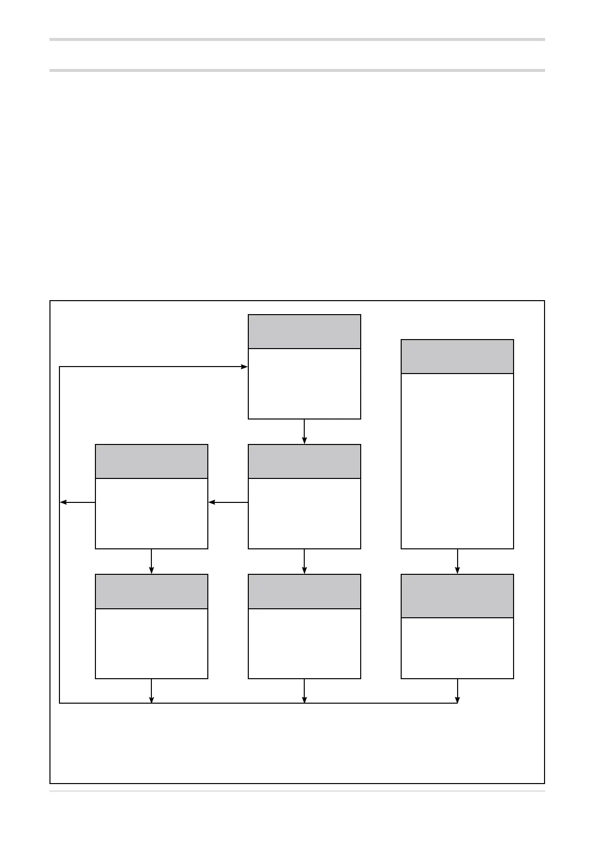
The following diagram shows how to use the key.
Each box represents a status, which is identified in the grey
area.