81901A “MSW_GPC-40/600A”_03-2021_ENG_page 77
3.16. Thermal protection alarms
Each SSR power module of the Advanced Power Controller
has:
• a temperature sensor for the internal heat sink;
• two additional temperature sensors connected to the
LINE and LOAD terminals;
• an “in-air” sensor to measure the board temperature.
The temperature values are stored in the variables In.Ntc.
SSR, In.Ntc.LINE, In.Ntc.LOAD and In.Ntc.AIR with a range
of 10.0...120.0 °C.
The following are also saved:
• in In.Ntc.SSR.Max1 and In.Ntc.SSR.Max2, the maxi-
mum temperature reached by In.Ntc.SSR;
• in In.Ntc.AIR.Max1 and In.Ntc.AIR.Max2, the maximum
temperature reached by In.Ntc.AIR.
The In.Ntc.SSR.Max1 and In.Ntc.AIR.Max1 temperatures
can be reset with a command.
The OVER_HEAT alarm is activated when at least one of
the temperatures exceeds a set threshold; there is also a
hysteresis to deactivate the alarm.
This condition could be caused by obstruction of the venti-
lation grill or blockage of the cooling fan.
With the OVER_HEAT alarm on, the control disables control
outputs OUT1, OUT2 and OUT3.
As an additional safety feature, the power modules are
equipped with maximum hardware temperature protection,
which disables the SSR commands.
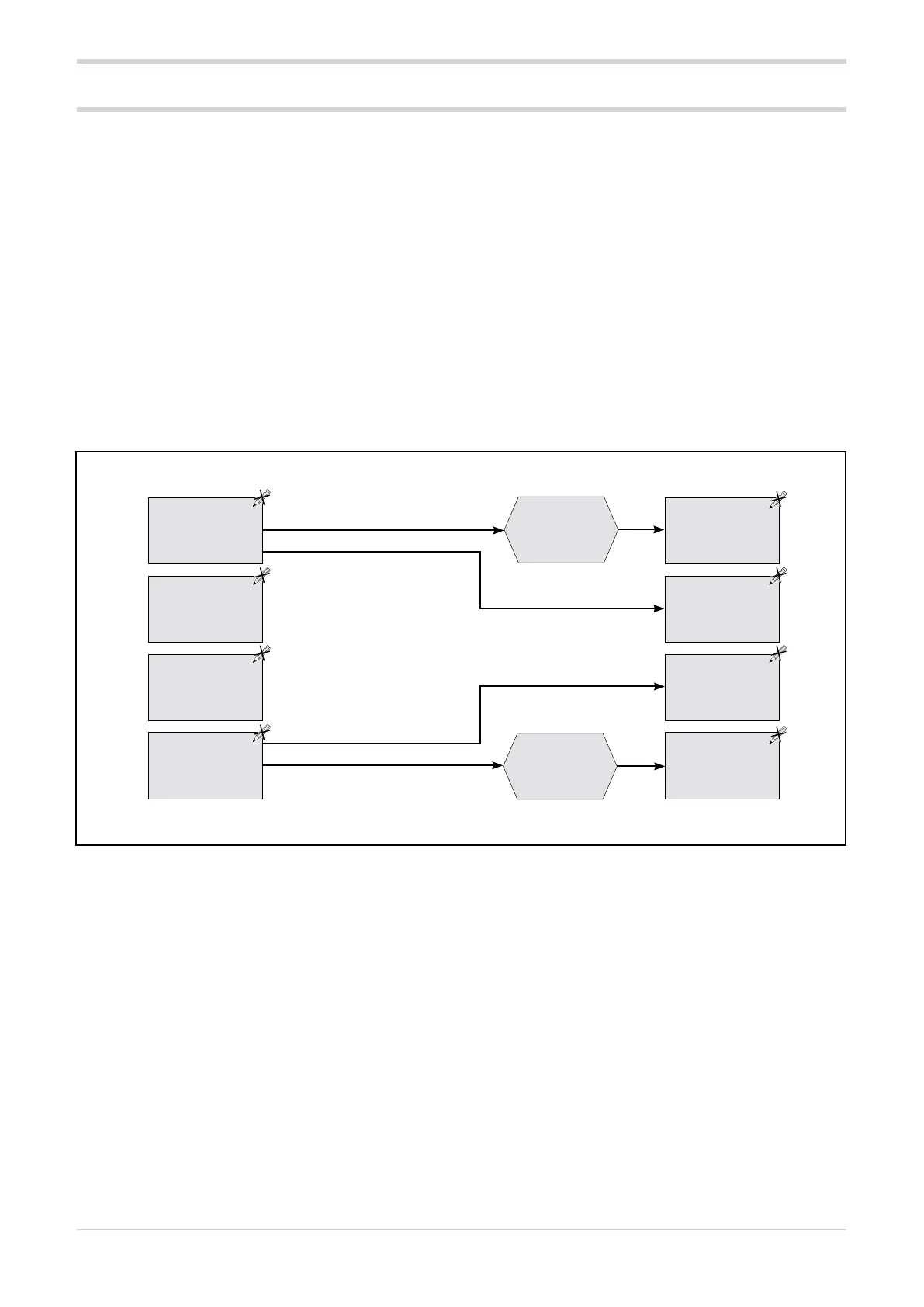
Functional diagram of thermal protection alarms
Reset max
temperature 1
RESET_INNTC_
MAX1_x
Reset max
temperature 1
RESET_INNTC_
MAX1_x
SSR heat sink
temperature value
In.Ntc.SSR_x
SSR heat sink
maximum
temperature value 1
In.Ntc.SSR.Max1_x
LINE terminal
temperature value
In.Ntc.LINE_x
SSR heat sink
maximum
temperature value 2
In.Ntc.SSR.Max2_x
LOAD terminal
temperature value
In.Ntc.LOAD_x
Board maximum
temperature value 2
In.Ntc.AIR.Max2_x
Board temperature
value
In.Ntc.AIR_x
Board maximum
temperature value 1
In.Ntc.AIR.Max1_x
with x = 1...3