81901A “MSW_GPC-40/600A”_03-2021_ENG_page 43
3.13.1. Enable alarms
Address
Format
GPC-OP
menu
Acronym
Global /
M/E1/E2
GF_eXpress menu
Attribute
Retentive
Type
Unit of mea-
surement
Default
Single-
node
Multi-
node
Description
1219
195 bit
05.01.01
AL.n
M
MainMenu → M → Alarms →
AL1...AL8 alarms → AL.n_1
R/W
■
Unsigned
Short
2312243 05.02.01 E1
MainMenu → E1 → Alarms →
AL1...AL8 alarms → AL.n_2
4291 05.03.01 E2
MainMenu → E2 → Alarms →
AL1...AL8 alarms → AL.n_3
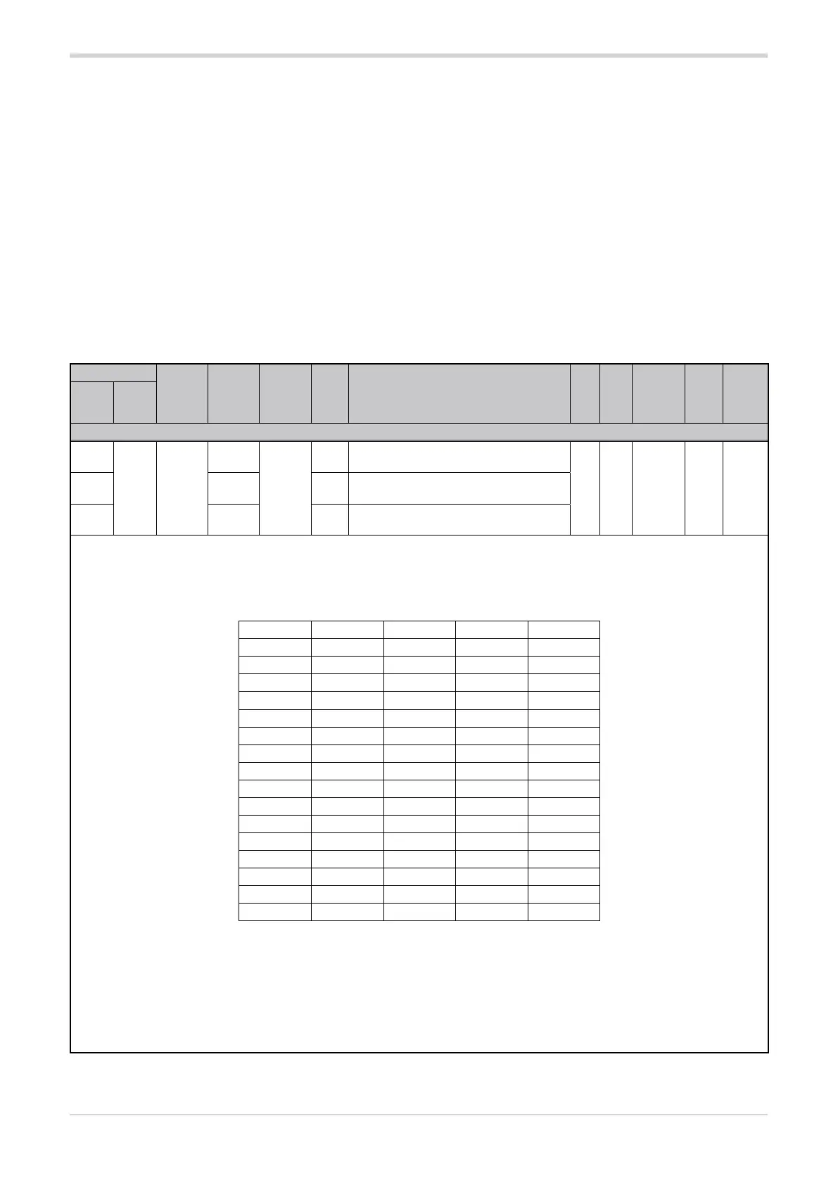
The parameter sets the generic alarms to be enabled. The combination of enabling and disabling is determined by the index set. The
following table shows the enabled alarms according to the index.
The default index 231 (= 7 + 32 + 64 + 128) enables alarms AL.1 + AL.2 + AL.3 (index 7), AL.5 (+32), AL.6 (+64) and AL.7 (+128).
Options:
Index Alarm 1 Alarm 2 Alarm 3 Alarm 4
0
1
■
2
3
■ ■
4
5
■
6
7
■ ■ ■
8
9
■
10
11
■ ■
12
13
■
14
15
■ ■ ■ ■
Increasing the index results in the following behaviours:
+16 to enable the HB alarm.
+32 to enable Alarm 5.
+64 to enable Alarm 6.
+128 to enable Alarm 7.
+256 to enable Alarm 8.
Example: Setting 19 (= 3 + 16) enables generic alarms 1 and 3, including their HB alarms, while all other alarms are disabled.
The default settings of the alarm definition parameters allow
the following to be configured for each module:
• AL1: Maximum line voltage alarm with time delay.
• AL2: Minimum line voltage alarm with time delay.
• AL3: Minimum current alarm with active output with
time delay disabled during softstart ramp.
• AL4: Alarm disabled.
• AL5: like AL1.
• AL6: like AL2.
• AL7: Maximum current alarm with active output with
time delay.
• AL8: Alarm disabled.
The minimum and maximum values depend on the current
and voltage ratings of the device.