81901 “MSW_GPC-40/600A”_03-2021_ENG_page 96
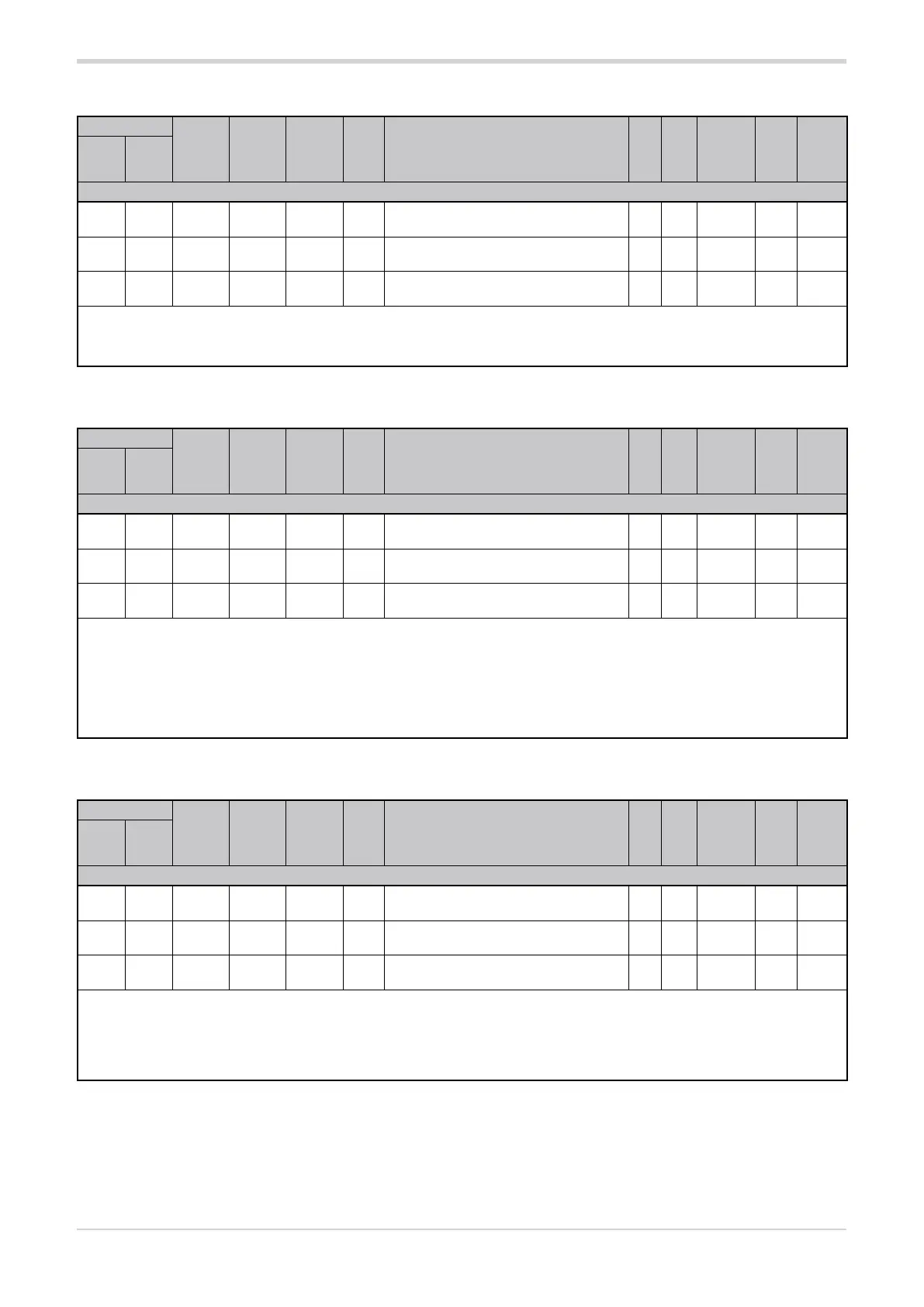
3.20.3. Lower analog output scale limit
Address
Format
GPC-OP
menu
Acronym
Global /
M/E1/E2
GF_eXpress menu
Attribute
Retentive
Type
Unit of mea-
surement
Default
Single-
node
Multi-
node
Description
1895 871 16 bit 06.05.03 LS.A01 Global
MainMenu → Global →
Outputs → Analog output1 → LS.AO1
R/W
■
Float
(####.#)
s.p. 0.0
1896 872 16 bit 06.06.03 LS.A02 Global
MainMenu → Global →
Outputs → Analog output2 → LS.AO2
R/W
■
Float
(####.#
s.p. 0.0
1897 873 16 bit 06.07.03 LS.A03 Global
MainMenu → Global →
Outputs → Analog output3 → LS.AO3
R/W
■
Float
(####.#
s.p. 0.0
The parameter sets the lower scale limit of analog outputs 1, 2 and 3, depending on the address used. The type of limit and the unit of
measurement are determined by the reference selected with parameter rF.AO1, rF.AO2 or rF.AO3.
min...max: 0.0...6553.5
3.20.4. Upper analog output scale limit
Address
Format
GPC-OP
menu
Acronym
Global /
M/E1/E2
GF_eXpress menu
Attribute
Retentive
Type
Unit of mea-
surement
Default
Single-
node
Multi-
node
Description
1898 874 16 bit 06.05.04 HS.A01 Global
MainMenu → Global →
Outputs → Analog output1 → HS.AO1
R/W
■
Float
(####.#
s.p. 100.0
1899 875 16 bit 06.06.04 HS.A02 Global
MainMenu → Global →
Outputs → Analog output2 → HS.AO2
R/W
■
Float
(####.#
s.p. 100.0
1900 876 16 bit 06.06.07 HS.A03 Global
MainMenu → Global →
Outputs → Analog output3 → HS.AO3
R/W
■
Float
(####.#
s.p. 100.0
The parameter sets the upper scale limit of analog outputs 1, 2 and 3, depending on the address used. The type of limit and the unit of
measurement are determined by the reference selected with parameter rF.AO1, rF.AO2 or rF.AO3.
The range of permissible values is limited at the lower end by the setting of parameter LS.AO1, LS.AO2 or LS.AO3, depending on the
address chosen.
min...max: LS.AO1...6553.5 (analog output 1)
LS.AO2...6553.5 (analog output 2)
LS.AO3...6553.5 (analog output 3)
3.20.5. Serial line value for analog output
Address
Format
GPC-OP
menu
Acronym
Global /
M/E1/E2
GF_eXpress menu
Attribute
Retentive
Type
Unit of mea-
surement
Default
Single-
node
Multi-
node
Description
1751 727 16 bit 10.01.23
SERIAL_
OUTA1
Global
MainMenu → Global → Expert →
Virtual → SERIAL_OUTA1
R/W
Float
(####.#
s.p. 0.0
1752 728 16 bit 10.01.24
SERIAL_
OUTA2
Global
MainMenu → Global → Expert →
Virtual → SERIAL_OUTA2
R/W
Float
(####.#
s.p. 0.0
1753 729 16 bit 10.01.25
SERIAL_
OUTA3
Global
MainMenu → Global → Expert →
Virtual → SERIAL_OUTA3
R/W
Float
(####.#
s.p. 0.0
The parameter sets the serial line value for analog outputs 1, 2 and 3, depending on the address used. The limits for analog outputs 1, 2
and 3 are defined by parameters LS.AO1 and HS.AO1, LS.AO1 and HS.AO1 and LS.AO1 and HS.AO1 respectively.
min...max: LS.AO1...HS.AO1 (analog output 1)
LS.AO2...HS.AO2 (analog output 2)
LS.AO3...HS.AO3 (analog output 3)