81901 “MSW_GPC-40/600A”_03-2021_ENG_page 20
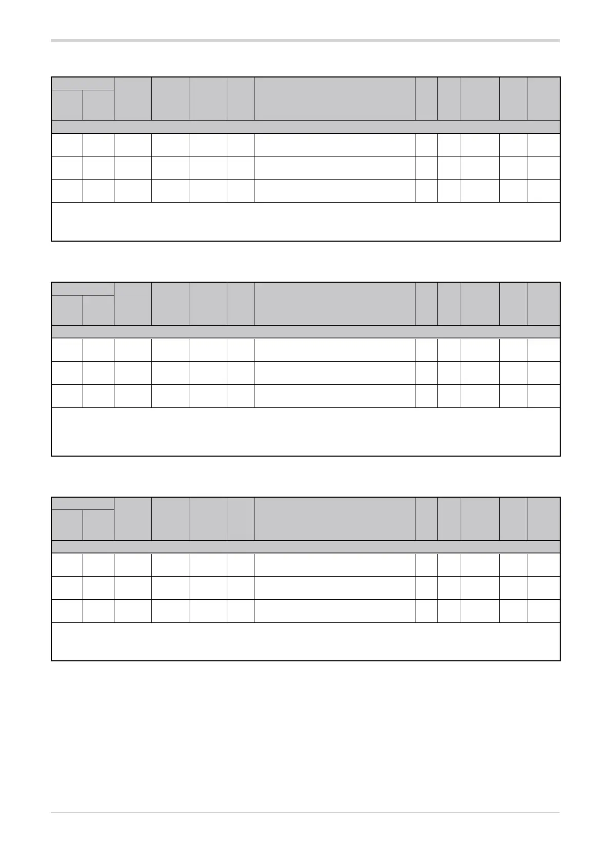
3.7.4. Analog input upper scale limit
Address
Format
GPC-OP
menu
Acronym
Global /
M/E1/E2
GF_eXpress menu
Attribute
Retentive
Type
Unit of mea-
surement
Default
Single-
node
Multi-
node
Description
1599 575 16 bit 04.05.03 HS.A1 Global
MainMenu → Global → Inputs →
Analog input 1 → HS.A1
R/W
■
Float
(####.#)
s.p. 100.0
1863 839 16 bit 04.06.03 HS.A2 Global
MainMenu → Global → Inputs →
Analog input 2 → HS.A2
R/W
■
Float
(####.#)
s.p. 100.0
1870 846 16 bit 04.07.03 HS.A3 Global
MainMenu → Global → Inputs →
Analog input 3 → HS.A3
R/W
■
Float
(####.#)
s.p. 100.0
The parameter sets the upper limit of the measuring scale used for analog input A1 or A2 or A3.
For examples of the use of the parameter, see paragraph “4.1. Setting parameters LS.A1/LS.A2/LS.A3 and HS.A1/HS.A2/HS.A3”.
min...max: LS.Ax...200.0
3.7.5. Analog input offset
Address
Format
GPC-OP
menu
Acronym
Global /
M/E1/E2
GF_eXpress menu
Attribute
Retentive
Type
Unit of mea-
surement
Default
Single-
node
Multi-
node
Description
1601 577 16 bit 04.05.04 oFS.A1 Global
MainMenu → Global → Inputs →
Analog input 1 → oFS.A1
R/W
■
Float
(####.#)
s.p. 0.0
1865 841 16 bit 04.06.04 oFS.A2 Global
MainMenu → Global → Inputs →
Analog input 2 → oFS.A2
R/W
■
Float
(####.#)
s.p. 0.0
1872 848 16 bit 04.07.04 oFS.A3 Global
MainMenu → Global → Inputs →
Analog input 3 → oFS.A3
R/W
■
Float
(####.#)
s.p. 0.0
The parameter sets the offset applied to the value read from analog input A1 or A2 or A3 to match the expected value. It is used to correct
a possible constant probe reading error.
This offset applies linearly to all readings, so it cannot be used to correct for probe linearity errors.
min...max: -99.9...99.9
3.7.6. Analog input low-pass filter
Address
Format
GPC-OP
menu
Acronym
Global /
M/E1/E2
GF_eXpress menu
Attribute
Retentive
Type
Unit of mea-
surement
Default
Single-
node
Multi-
node
Description
1600 576 16 bit 04.05.05 FLt.A1 Global
MainMenu → Global → Inputs →
Analog input 1 → FLt.A1
R/W
■
Float
(####.#)
sec. 0.1
1864 840 16 bit 04.06.05 FLt.A2 Global
MainMenu → Global → Inputs →
Analog input 2 → FLt.A2
R/W
■
Float
(####.#)
sec. 0.1
1871 847 16 bit 04.07.05 FLt.A3 Global
MainMenu → Global → Inputs →
Analog input 3 → FLt.A3
R/W
■
Float
(####.#)
sec. 0.1
The parameter sets the time constant value of the digital low-pass filter applied to analog input A1 or A2 or A3. The filter calculates the
average of the values read in the specified time interval. With 0.0 no filter is applied.
min...max: 0.0...20.0