81901 “MSW_GPC-40/600A”_03-2021_ENG_page 72
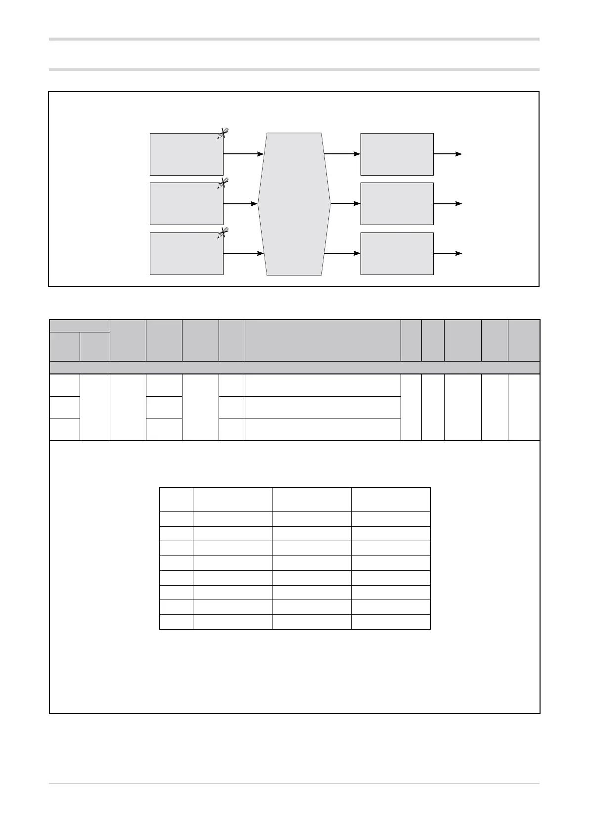
Functional diagram of Power Fault alarms
3.15. POWER_FAULT alarms (SSR_SHORT, NO_VOLTAGE and NO_CURRENT)
Enabling
Power Fault
alarms
hd.2
Time filter
dG.F
Update
frequency
dG.t
Alarm status
NO_VOLTAGE
Alarm status
SSR_SHORT
Alarm status
NO_CURRENT
Control output value
Ou.P
Filtered CT ammeter
input value at acti-
vated output I.on
Filtered VT voltme-
ter input value
I.VF
3.15.1. Enable POWER_FAULT alarms
Address
Format
GPC-OP
menu
Acronym
Global /
M/E1/E2
GF_eXpress menu
Attribute
Retentive
Type
Unit of mea-
surement
Default
Single-
node
Multi-
node
Description
1684
660 16 bit
05.07.01
hd.2
M
MainMenu → M → Alarms →
PF alarms → hd.2_1
R/W
■
Unsigned
Short
112708 05.08.01 E1
MainMenu → E1 → Alarms →
PF alarms → hd.2_2
4756 05.09.01 E2
MainMenu → E2 → Alarms →
PF alarms → hd.2_3
The parameter sets the POWER_FAULT alarms: SSR_SHORT (SSR short circuit), NO_VOLTAGE (voltage failure) and NO_CURRENT (cur-
rent failure). Active alarms are identified and set with an index.
The index 0 deactivates all 3 alarms.
Options:
Index SSR_SHORT alarm
on
NO_VOLTAGE
alarm on
NO_CURRENT
alarm on
0
1
■
2
■
3
■ ■
8
■
9
■ ■
10
■ ■
11
■ ■ ■
Notes:
Increasing the index by a fixed amount results in the following behaviours:
Index + 32 = POWER_FAULT alarm storage is enabled.
Index + 64 = Current polarity control is disabled (only for inductive loads).
Examples:
Setting index 35 (= 3 + 32) enables SSR_SHORT and NO_VOLTAGE alarms with alarm storage.
Setting index 73 (= 9 + 64), with an inductive load, enables SSR_SHORT and NO_CURRENT alarms without polarity check for current.