81901A “MSW_GPC-40/600A”_03-2021_ENG_page 31
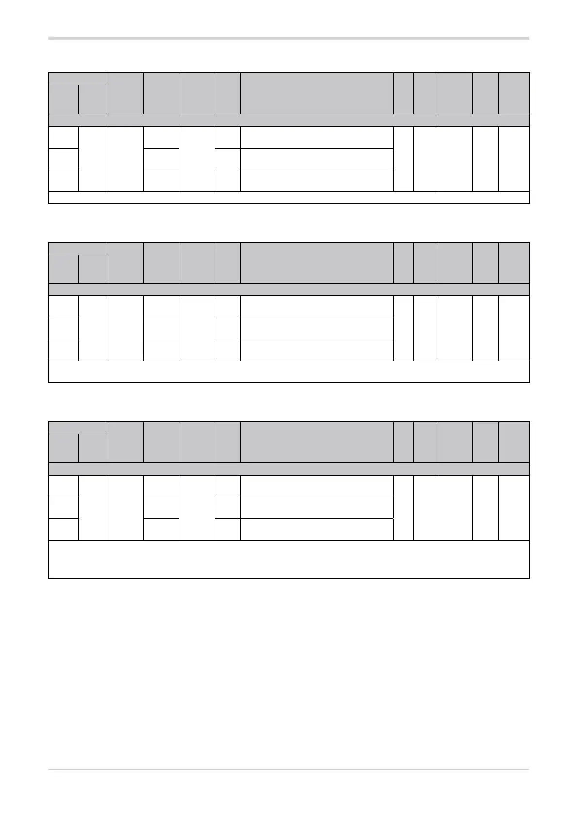
3.10.1. Lower VT voltmeter input scale limit
Address
Format
GPC-OP
menu
Acronym
Global /
M/E1/E2
GF_eXpress menu
Attribute
Retentive
Type
Unit of mea-
surement
Default
Single-
node
Multi-
node
Description
1477
453 16 bit
04.09.01
L.tV
M
MainMenu → M → Inputs →
VT line input → L.tV_1
R
Float
(####.#)
V 60.02501 04.13.01 E1
MainMenu → E1 → Inputs →
VT line input → L.tV_2
4549 04:15:01 E2
MainMenu → E2 → Inputs →
VT line input → L.tV_3
The parameter shows the lower limit of the line voltage measurement scale used for the voltmeter input.
3.10.2. Upper VT voltmeter input scale limit
Address
Format
GPC-OP
menu
Acronym
Global /
M/E1/E2
GF_eXpress menu
Attribute
Retentive
Type
Unit of mea-
surement
Default
Single-
node
Multi-
node
Description
1434
410 16 bit
04.09.02
H.tV
M
MainMenu → M → Inputs →
VT line input → H.tV_1
R
Float
(####.#)
V
see
table
para-
graph
3.9.6
2458 04:13:02 E1
MainMenu → E1 → Inputs →
VT line input → H.tV_2
4506 04:15:02 E2
MainMenu → E2 → Inputs →
VT line input → H.tV_3
The parameter shows the upper limit of the line voltage measurement scale used for the voltmeter input.
The default value of the upper limit depends on the controller model (see the table in paragraph “3.9.6. Upper voltmeter input scale limit”).
3.10.3. VT voltage transformer input offset
Address
Format
GPC-OP
menu
Acronym
Global /
M/E1/E2
GF_eXpress menu
Attribute
Retentive
Type
Unit of mea-
surement
Default
Single-
node
Multi-
node
Description
1435
411 16 bit
04.09.03
o.tV
M
MainMenu → M → Inputs →
VT line input → o.tV_1
R/W
■
Float
(####.#)
V 0.02459 04.12.03 E1
MainMenu → E1 → Inputs →
VT line input → o.tV_2
4507 04:15:03 E2
MainMenu → E2 → Inputs →
VT line input → o.tV_3
The parameter sets the offset applied to the line voltage value read at the input of the VT voltage transformer to match the expected val-
ue. Its function is to correct a possible constant reading error. This offset applies linearly to all readings.
min...max: -99.9...99.9