81901A “MSW_GPC-40/600A”_03-2021_ENG_page 101
3.22. Automatic - manual control
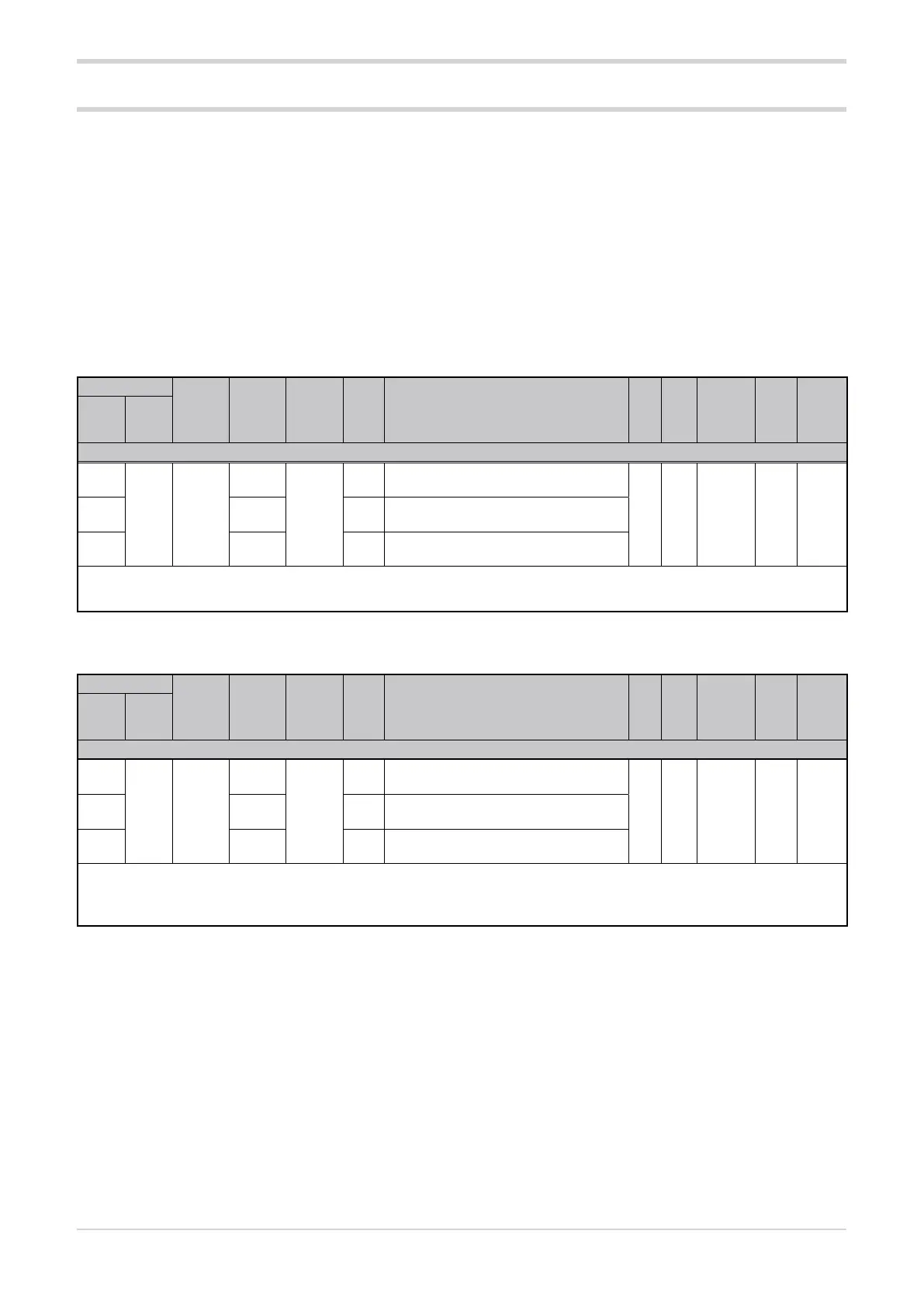
3.22.1. Manual power
Address
Format
GPC-OP
menu
Acronym
Global /
M/E1/E2
GF_eXpress menu
Attribute
Retentive
Type
Unit of mea-
surement
Default
Single-
node
Multi-
node
Description
1276
252 16 bit
07.02.01
MAN-
UAL_
POWER
M
MainMenu → M → Controls →
MANUAL_POWER_1
R/W
■
Float
(####.#)
% 0.02300 07.03.01 E1
MainMenu → E1 → Controls →
MANUAL_POWER_2
4348 01.04.01 E2
MainMenu → E2 → Controls →
MANUAL_POWER_3
The parameter sets the percentage of manual power.
min...max: -100.0...100.0
3.22.2. Automatic - manual selection
Address
Format
GPC-OP
menu
Acronym
Global /
M/E1/E2
GF_eXpress menu
Attribute
Retentive
Type
Unit of mea-
surement
Default
Single-
node
Multi-
node
Description
1025
1 bit
12.01.01
BIT_
AUTO_
MAN
M
MainMenu → M → Expert →
Bit → BIT_AUTO_MAN_1
R/W
■
Unsigned
Short
OFF2049 12.02.01 E1
MainMenu → E1 → Expert →
Bit → BIT_AUTO_MAN_2
4097 12.03.01 E2
MainMenu → E2 → Expert →
Bit → BIT_AUTO_MAN_3
The bit sets the automatic/manual operation of the Advanced Power Controller.
Options: OFF = Automatic
ON = Manual
The digital input function can be used to put the Advanced
Power Controller in MAN (manual) status and set the control
output to a constant value, which can be changed via serial
communication.
When returning to AUTO (automatic) status, the transition
from manual mode will be based upon the reference power
(SPU_x) and the control output gradient (G.out).
In addition to the parameters shown below, the following
parameters should also be considered for automatic - man-
ual control:
• digital input function dIG.1 / dIG.2 / dIG.3 / dIG.4 (see
paragraph “3.12.4. Digital input function”);
• value of the control output Ou.P (see paragraph
“3.21.2. Output power value”).