81901 “MSW_GPC-40/600A”_03-2021_ENG_page 128
3.35.9. Jumper / DIP switch status
Address
Format
GPC-OP
menu
Acronym
Global /
M/E1/E2
GF_eXpress menu
Attribute
Retentive
Type
Unit of mea-
surement
Default
Single-
node
Multi-
node
Description
1370 346 16 bit 02.07
JUMPER_
STATUS
Global
MainMenu → Global → Info →
JUMPER_STATUS
R
Unsigned
Short
0
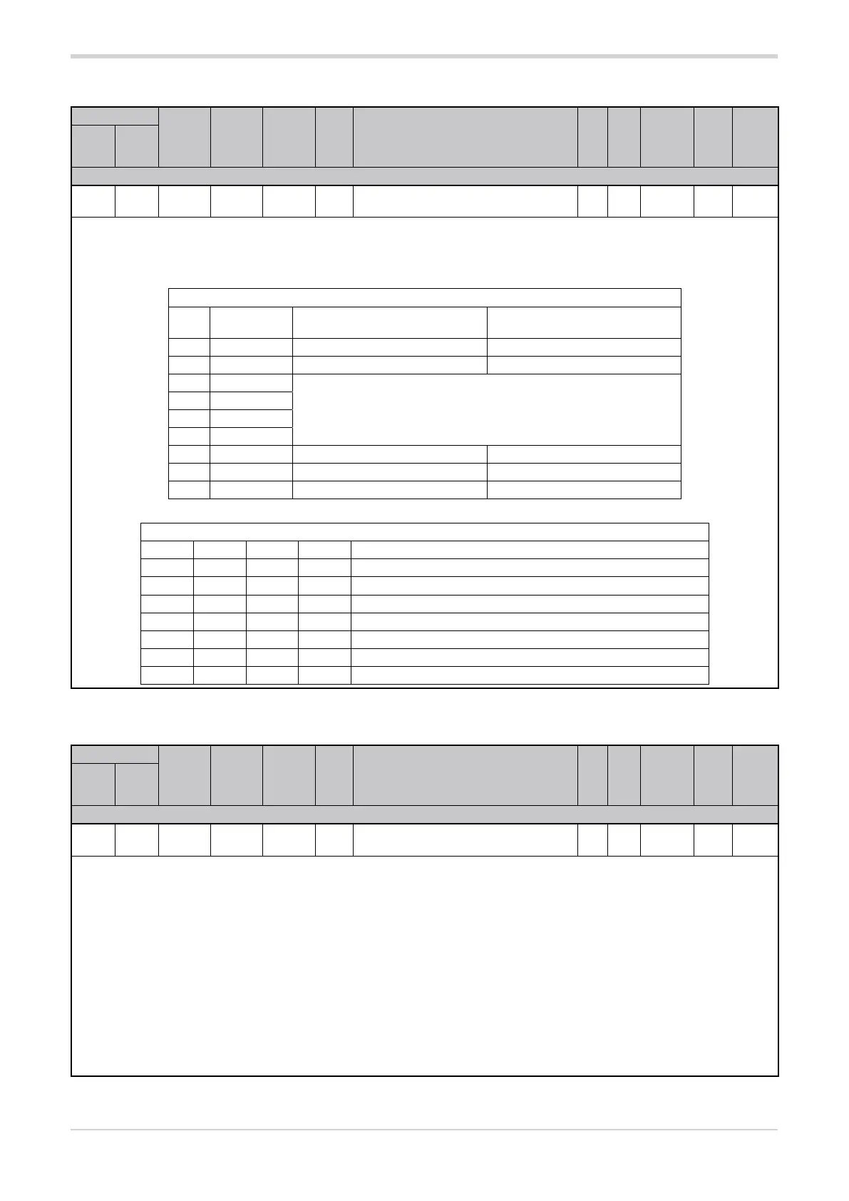
The register shows the status of the jumpers / DIP switches. The status of the individual jumper / DIP switch can determine a specific
configuration.
The combination of the status of jumpers / DIP switches S7-1, S7-2, S7-3 and S7-4 determines the operating mode.
Options:
Configuration
bit Jumper /
DIP switch
Status OFF Status ON
0 S1
1 S2
2 S7-1
see table DIP switch status S7-1...S7-4
3 S7-2
4 S7-3
5 S7-4
6 S7-5 Resistive load Inductive load
7 S7-6 Default parameter configuration
8 S7-7 Single-node mode Multi-node mode
DIP switch status S7-1...S7-4
S7-1 S7-2 S7-3 S7-4 Operating modes
OFF OFF OFF OFF 3 single-phase loads
OFF ON OFF OFF 3 independent single-phase open delta loads
ON ON OFF OFF three-phase open delta/star load with neutral
ON ON ON OFF three-phase closed delta load
ON OFF OFF ON three-phase star load without neutral
ON OFF OFF OFF three-phase star load without neutral with TWO-PHASE control
ON OFF ON OFF three-phase closed delta load with TWO-PHASE control
3.35.10. Enabling virtual DIP switch control
Address
Format
GPC-OP
menu
Acronym
Global /
M/E1/E2
GF_eXpress menu
Attribute
Retentive
Type
Unit of mea-
surement
Default
Single-
node
Multi-
node
Description
1797 773 16 bit 03.01.06 J.Set Global
MainMenu → Global → Parameters →
J.Set
R/W
■
Unsigned
Short
0
The factory configuration has the hardware DIP switch control active (J.Set = 0). Setting parameter J.Set = 1 enables the control of virtual
DIP switches via serial.
When virtual control is active, the configuration considered is not that described by the hardware DIP switches but that shown in the J.SEr
parameter (for the writing of J.SEr refer to the table in paragraph “3.35.9. Jumper / DIP switch status”).
The S7 hardware DIP switches in positions 1-2-3-4-5-7 are no longer considered while the S7 hardware DIP switch in position 6 (forced
CGF) if active (ON) has priority over the virtual DIP switches, returning the parameters J.Set and J.Ser to zero after a restart.
NOTE: Any change in the hardware DIP-Switches and J.Set and J.Ser parameters will only be active after a restart.
NOTE: As with control of hardware DIP-Switches, also for virtual control, following a change in the configuration, the parameter initial-
isation procedure must be performed after a configuration change by setting the virtual DIP-Switch position 6 (forced CGF) to ON and
restarting the product.
Options: 0 = Hardware DIP switch priority
1 = Virtual DIP switch priority (from serial line)