81901 “MSW_GPC-40/600A”_03-2021_ENG_page 142
5.3. Operations
5.3.1. HOME screen
E2 E1 M
V 230 230 230
A 200 200 200
KW 46 46 46
The screen gives a summary of the basic GPC parameters:
• voltage on the load (V),
• current in the load (A)
• power on load (KW)
of the three modules.
The screen is displayed:
• with the GPC is switched on (keypad already connect-
ed),
• when connecting the keypad to the GPC (in the ab-
sence of alarms),
• by pressing the HOME button.
5.3.2. Accessing the menu
To access the menu, press the MENU button.
The keypad checks whether a password has been set (con-
figurable via GF_eXpress).
If the password has not been enabled (PASS.C = 0), the
menus are accessed directly.
If the password is enabled (PASS.C > 0), it displays the
screen on which to enter the numeric password (PASS-
WORD = PASS.C) which allows access to the menus, if the
value entered is correct.
02.01 ADDR: 10 - 889
PASSWORD:
Def: 0
If the password entered is incorrect, you return to HOME.
The entered password will remain valid until the GPC-OP is
disconnected from the GPC or the HOME or ALARM button
is pressed.
For instructions on changing your password, see paragraph
“5.3.5. Changing a numerical parameter”.
5.3.3. Browsing the menus
Press the ► key to enter the submenu or parameter. The
same result is obtained by pressing the ENTER key.
Press the ► key twice to return to the main menu.
Press the ▼ and ▲ keys to scroll through the various menu
items.
Each menu item is preceded by a numerical address with
2-digits (1st level menu), 4-digits (2nd level menu) or 6-dig-
its (3rd level menu). The address digits are grouped in twos
and separated by a dot.
04.01 STATUS M
04.02 STATUS E1
04.03 STATUS E2
04.04 ANALOG In.A1
04.05 ANALOG In.A2
In the above screenshot, the parameter ANALOG In.A2 has
address 04.05, i.e., the fourth item in the first-level menu
and the fifth item in the corresponding second-level menu.
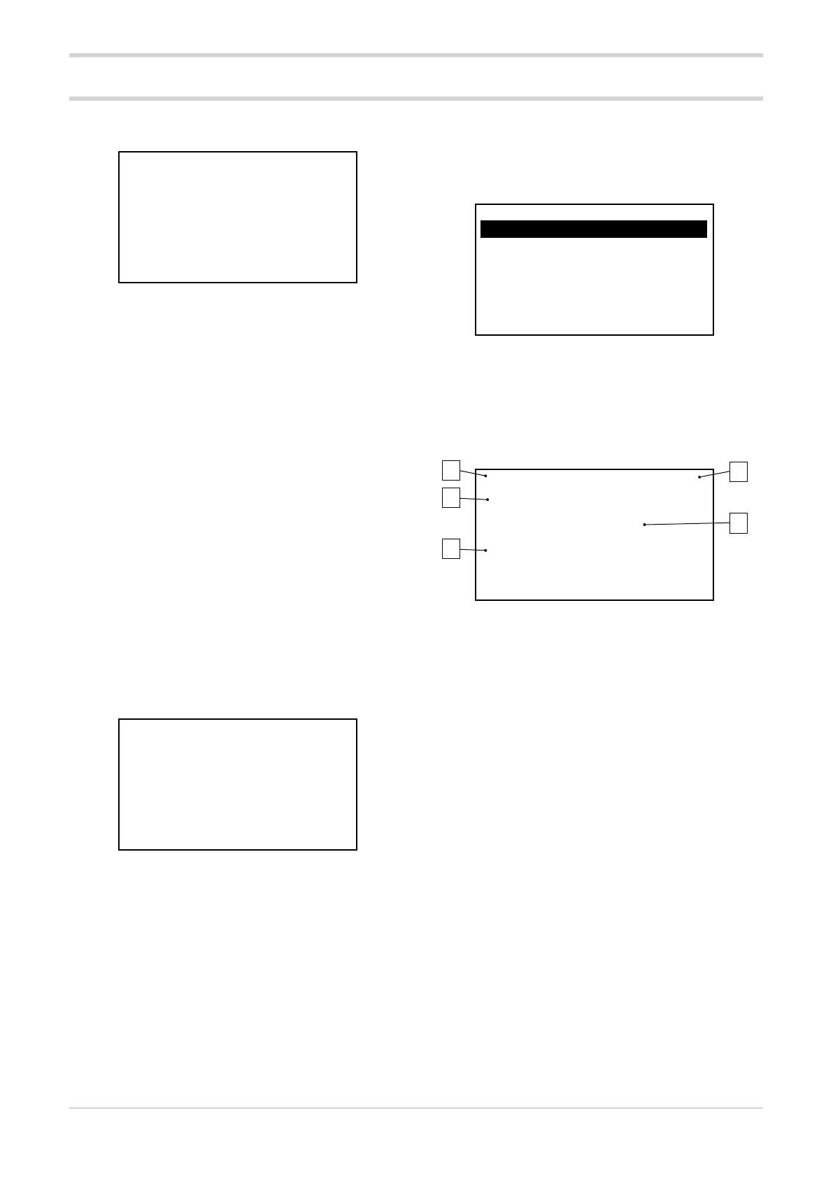
5.3.4. Parameter display
04.04.01 ADDR: 10 - 573
Tp.A1: input type
1
Def: 1
1. Indication of menu index and parameter position.
2. Modbus address of the parameter in node-address
format (in the image node = 10, address = 573).
3. Parameter description.
4. Parameter value:
• Numerical parameter: the numerical value of the pa-
rameter is displayed in the required format, together
with the unit of measurement.
• Binary parameter: the 16 data bits are displayed in
succession by pressing the ►key.
• Status parameter (COMMANDS menu): the status
description is displayed.
5. Additional information depending on the type of pa-
rameter:
• Numerical parameter: the default, minimum and
maximum values of the parameter are displayed.
These values are shown in sequence by pressing the
► button (only if the parameter is R/W).
When setting the R/W parameter, any Out of range
error condition of the entered value is shown.
• Binary parameter: displays the status (ON-OFF,
AUTO-MAN, ...) of the bits selected in sequence by
pressing the ►key.
1
3
5
2
4