81901 “MSW_GPC-40/600A”_03-2021_ENG_page 86
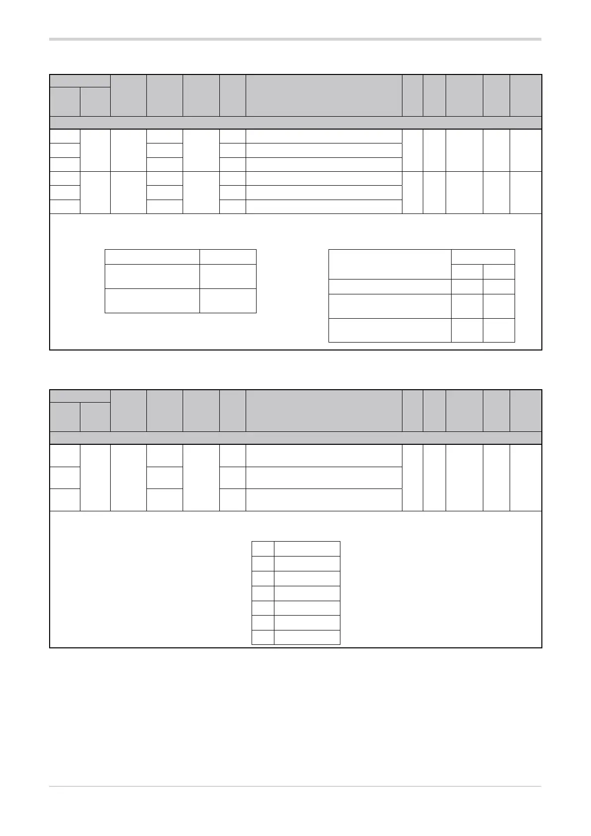
3.19.2. OUT cycle time
Address
Format
GPC-OP
menu
Acronym
Global /
M/E1/E2
GF_eXpress menu
Attribute
Retentive
Type
Unit of mea-
surement
Default
Single-
node
Multi-
node
Description
1033
9 16 bit
06.01.07
Ct.1
M
MainMenu → M → Outputs → Ct.1_1
R/W
■
Float sec.
see
table
2057 06.02.07 E1
MainMenu → E1 → Outputs → Ct.1_2
4105 06.03.07 E2
MainMenu → E2 → Outputs → Ct.1_3
1183
159 16 bit
06.01.08
Ct.2
M
MainMenu → M → Outputs → Ct.2_1
R/W
■
Float sec. 202207 06.02.08 E1
MainMenu → E1 → Outputs → Ct.2_2
4255 06.03.08 E2
MainMenu → E2 → Outputs → Ct.2_3
The parameter sets the OUT1 and OUT2 cycle time, depending on the address used. The cycle time is the duration of a series of conduc-
tion and non-conduction cycles in the same ratio as the power to be transferred to the load.
The value of the parameter depends on the type of trigger.
3.19.3. Status rL.x (MASKOUT_RL)
Address
Format
GPC-OP
menu
Acronym
Global /
M/E1/E2
GF_eXpress menu
Attribute
Retentive
Type
Unit of mea-
surement
Default
Single-
node
Multi-
node
Description
1332
308 16 bit
01.02.23
MASK-
OUT_RL
M
MainMenu → M → Status →
MASKOUT_RL_1
R
Unsigned
Short
2356 01.03.23 E1
MainMenu → E1 → Status →
MASKOUT_RL_2
4404 01.04.23 E2
MainMenu → E2 → Status →
MASKOUT_RL_3
The parameter bits show the status of the output reference signals.
Options:
bit Signal
0 Status rL.1
1 Status rL.2
2 Status rL.3
3 Status rL.4
4 Status rL.5
5 Status rL.6
DIP switch position 5 Default Ct.1
OFF
(resistive load)
0
ON
(inductive load)
4
Type of trigger
Parameter
min max
BF 0 0
ZC with slow cycle time
(see setting rL.1)
0 200
ZC with fast cycle time
(see setting rL.1)
0.1 20.0