81901A “MSW_GPC-40/600A”_03-2021_ENG_page 17
3.6. Connections
In a network, a “Master” device can be identified, which
communicates through commands, and “Slave” devices,
which interpret and implement the commands. The GPC
devices are the Slaves and the Master is the supervisor
terminal or a PLC.
Each GPC device is equipped with an opto-isolated RS485
serial port (PORT 1 or serial 1) which uses the standard
Modbus protocol. The connectors used are J8 and J9
(RJ10 type). An additional optional serial interface (PORT 2
or serial 2) can also be inserted into the device to connect
to the required fieldbus. Interfaces are available for con-
nection to Modbus, Profibus DP, CANopen and Ethernet
(Modbus TCP, EtherCAT and EthernetIP).
A parameter can be read or written from both PORT 1 and
PORT 2 and both communication ports respond to the
same Cod address.
3.6.1. Modbus network installation
The procedure described below is for the Modbus protocol.
For the remaining protocols, please refer to the specific
fieldbus manuals available at www.gefran.com.
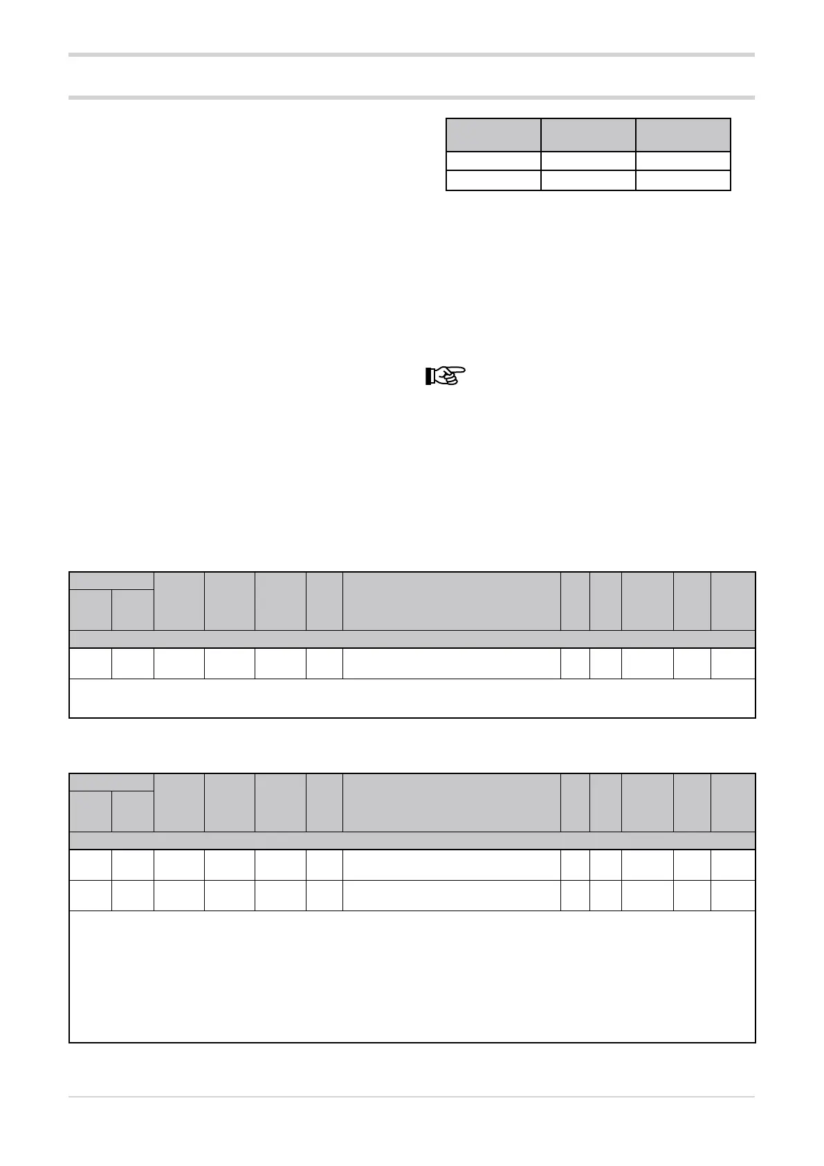
GPC devices leave the factory with the following settings:
• Cod = 0 (rotary switches set 0 + 0)
PORT 1
(Serial 1)
PORT 2
(Serial 2)
Speed (bit/s) 19200 19200
Parity No parity No parity
In summary, the valid settings on the rotary switches (tens
+ units) are:
• (0 + 0) = Autobaud Serial 1
• (B + 0) = Autobaud Serial 2
The communication parameters for PORT 1 are bAu, which
allows the speed to be set in bits/s, and Par, which allows
the parity to be set
. The corresponding parameters for
PORT 2 are bAu.2 and PAr2.
Changing the parameters bAu and PAr may invali-
date the communication.
3.6.2. Communication error
If a communication error occurs between the GPC device
and the Master device, it is possible to force an output
power value (C.E.P parameter of each module) and transmit
the alarm status to a relay output (rL.x parameters).
If the communication error is caused by the timeout, the
timeout time can be changed in the C.E.t parameter.
3.6.3. Device identification code
Address
Format
GPC-OP
menu
Acronym
Global /
M/E1/E2
GF_eXpress menu
Attribute
Retentive
Type
Unit of mea-
surement
Default
Single-
node
Multi-
node
Description
1070 46 16 bit 02.09 Cod Global
MainMenu → Global → Info → Cod
R
Unsigned
Short
10
The parameter shows the identification code of the GPC device, which is set with the hexadecimal rotary switches.
min...max: 1...99
3.6.4. Serial port transmission speed
Address
Format
GPC-OP
menu
Acronym
Global /
M/E1/E2
GF_eXpress menu
Attribute
Retentive
Type
Unit of mea-
surement
Default
Single-
node
Multi-
node
Description
1069 45 16 bit 03.01.01 bAu Global
MainMenu → Global → Info → bAu
R/W
■
Unsigned
Short
4
1650 626 16 bit 03.01.03 bAu.2 Global
MainMenu → Global → Info → bAu.2
R/W
■
Unsigned
Short
4
The parameter sets the transmission speed of the serial port.
Options: 0 = Speed 1200 bit/s
1 = Speed 2400 bit/s
2 = Speed 4800 bit/s
3 = Speed 9600 bit/s
4 = Speed 19200 bit/s
5 = Speed 38400 bit/s
6 = Speed 57600 bit/s
7 = Speed 115200 bit/s