81901A “MSW_GPC-40/600A”_03-2021_ENG_page 41
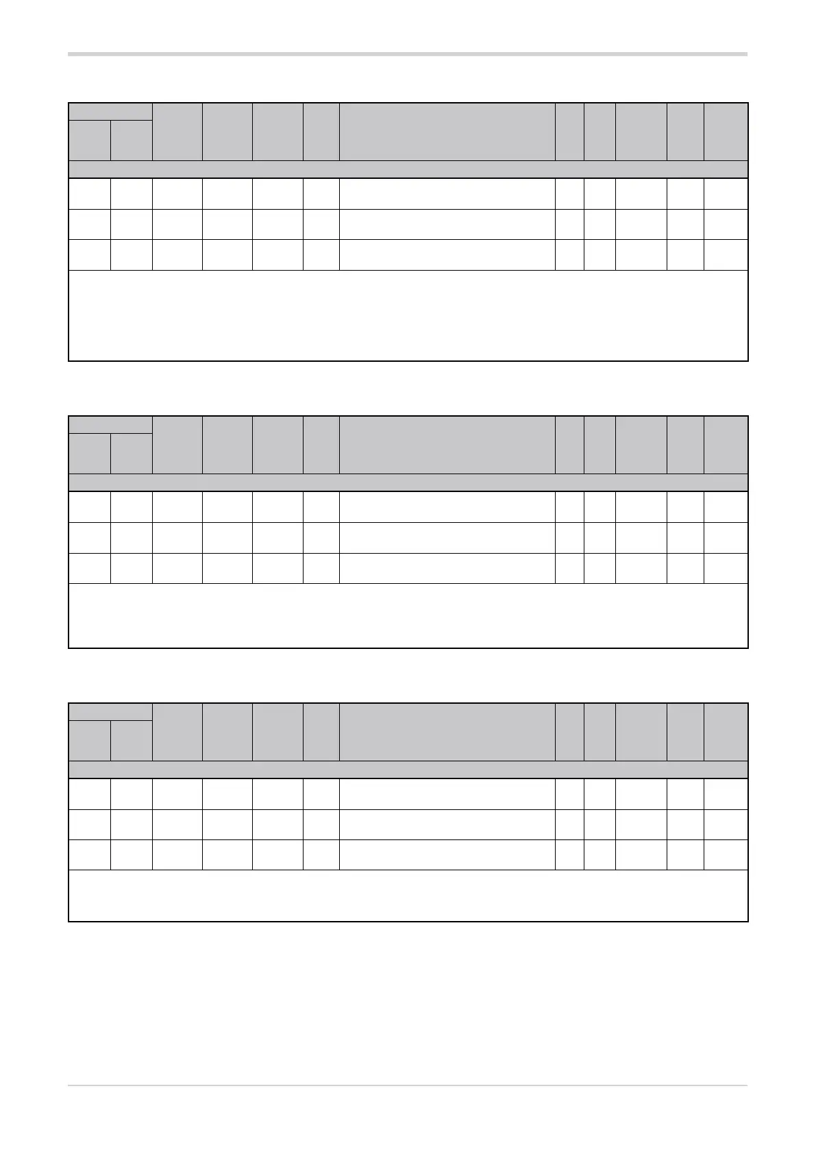
3.12.5. PWM input timeout
Address
Format
GPC-OP
menu
Acronym
Global /
M/E1/E2
GF_eXpress menu
Attribute
Retentive
Type
Unit of mea-
surement
Default
Single-
node
Multi-
node
Description
1380 356 16 bit 04:17:09 PWm.t1 Global
MainMenu → Global → Inputs →
Digital inputs → PWm.t1
R/W
■
Float
(####.#)
sec. 0.01
1381 357 16 bit 04:17:10 PWm.t2 Global
MainMenu → Global → Inputs →
Digital inputs → PWm.t2
R/W
■
Float
(####.#)
sec. 1.00
1386 362 16 bit 04:17:11 PWm.t3 Global
MainMenu → Global → Inputs →
Digital inputs → PWm.t3
R/W
■
Float
(####.#)
sec. 1.00
The parameter sets the timeout for the digital input PWM 1, PWM 2 or PWM 3, depending on the address used.
IMPORTANT! If the digital input is used to control the power percentage (parameter Ou.P) to be delivered on the load (PWM input func-
tion, dIG = 7), the parameter PWm.t must be set to a value equal to or greater than the period of the PWM control signal used, in order to
guarantee the reaction time even in static conditions of low (Ou.P = 0%) or high (Ou.P=100%) input.
min...max: 0.01...10.00
3.12.6. Digital filter for PWM input
Address
Format
GPC-OP
menu
Acronym
Global /
M/E1/E2
GF_eXpress menu
Attribute
Retentive
Type
Unit of mea-
surement
Default
Single-
node
Multi-
node
Description
1462 438 16 bit 04:17:06 Ft.PWm1 Global
MainMenu → Global → Inputs →
Digital inputs → Ft.PWm1
R/W
■
Float
(####.#)
sec. 0.1
1396 372 16 bit 04:17:07 Ft.PWm2 Global
MainMenu → Global → Inputs →
Digital inputs → Ft.PWm2
R/W
■
Float
(####.#)
sec. 0.1
1397 373 16 bit 04:17:08 Ft.PWm3 Global
MainMenu → Global → Inputs →
Digital inputs → Ft.PWm3
R/W
■
Float
(####.#)
sec. 0.1
This parameter sets the value of the digital filter time constant applied to the value read from digital input PWM 1, PWM 2 or PWM 3,
depending on the address used. The filter calculates the average of the values read in the specified time interval.
With 0.0 no filter is applied.
min...max: 0.0...20.0
3.12.7. PWM input value
Address
Format
GPC-OP
menu
Acronym
Global /
M/E1/E2
GF_eXpress menu
Attribute
Retentive
Type
Unit of mea-
surement
Default
Single-
node
Multi-
node
Description
1542 518 16 bit 04.01.04 In.Pwm1 Global
MainMenu → Global → Status → In.Pwm1
R
Float
(####.#)
%
1459 435 16 bit 04.01.05 In.Pwm2 Global
MainMenu → Global → Status → In.Pwm2
R
Float
(####.#)
%
1481 457 16 bit 04.01.06 In.Pwm3 Global
MainMenu → Global → Status → In.Pwm3
R
Float
(####.#)
%
The parameter shows the value of the input PWM 1, PWM 2 or PWM 3, depending on the address used, as a percentage of the ON state
compared to the ON + OFF period.
min...max: 0.0...100.0