81901 “MSW_GPC-40/600A”_03-2021_ENG_page 108
3.27.2. Maximum RMS current limit in steady state
Address
Format
GPC-OP
menu
Acronym
Global /
M/E1/E2
GF_eXpress menu
Attribute
Retentive
Type
Unit of mea-
surement
Default
Single-
node
Multi-
node
Description
1731
707 16 bit
09.01.02
Fu.tA
M
MainMenu → M → Power controls →
Fu.tA_1
R/W
■
Float
(####.#)
A
see
table
2755 09.02.02 E1
MainMenu → E1 → Power controls →
Fu.tA_2
4803 09.03.02 E2
MainMenu → E2 → Power controls →
Fu.tA_3
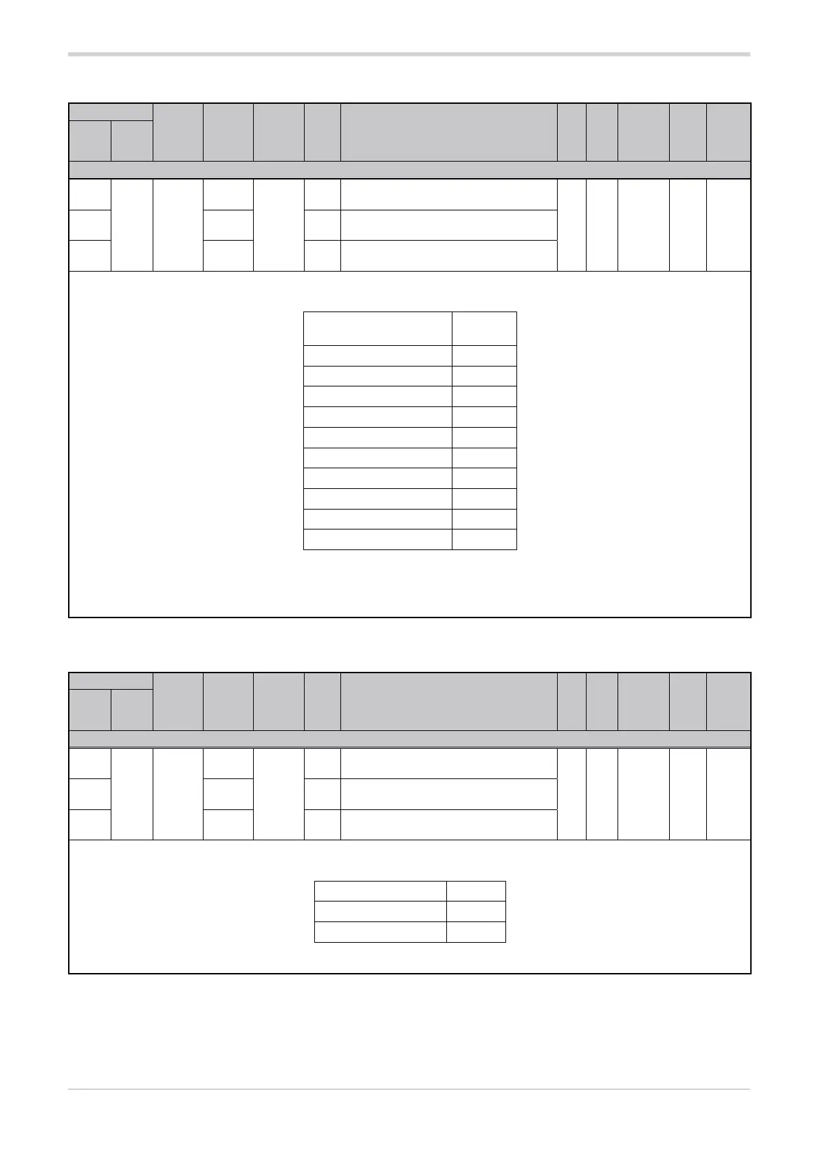
The parameter sets the maximum limit of the RMS current at steady state.
The default value depends on the size of the controller:
Size GPC-M, GPC-E1,
GPC-E2
Default
40 A 40.0
60 A 60.0
100 A 100.0
150 A 150.0
200 A 200.0
250 A 250.0
300 A 300.0
400 A 400.0
500 A 500.0
600 A 600.0
With a three-phase load, a different Fu.tA parameter value can be set for each module. This allows, for example, control of an unbalanced
three-phase load.
min...max: 0.0...3275.0
3.27.3. Minimum number of cycles of BF mode
Address
Format
GPC-OP
menu
Acronym
Global /
M/E1/E2
GF_eXpress menu
Attribute
Retentive
Type
Unit of mea-
surement
Default
Single-
node
Multi-
node
Description
1728
704 16 bit
09.01.03
Bf.Cy
M
MainMenu → M → Power controls →
Bf.Cy_1
R/W
■
Unsigned
Short
see
table
2752 09.02.03 E1
MainMenu → E1 → Power controls →
Bf.Cy_2
4800 09.03.03 E2
MainMenu → E2 → Power controls →
Bf.Cy_3
The parameter sets the minimum number of BF mode cycles.
The default value of the parameter depends on the setting of DIP switch 5:
DIP switch 5 position Default
OFF (resistive load) 1
ON (inductive load) 5
min...max: 1...10