81901A “MSW_GPC-40/600A”_03-2021_ENG_page 59
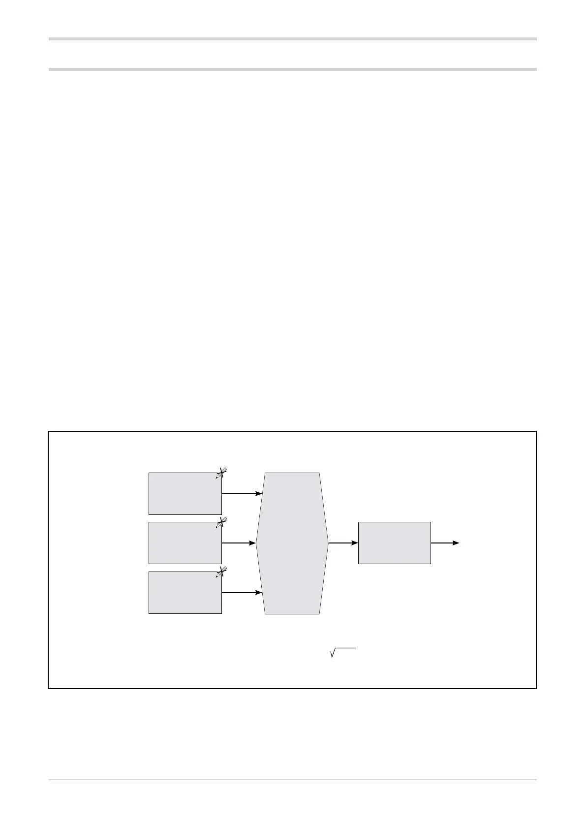
Functional diagram of HB alarm single-phase load
3.14. HB (Heater Break) Alarms
An alarm threshold teach-in function is also available.
The function can be activated by a command from a serial
line, a digital input (see paragraph “3.12.4. Digital input
function”) or a key (see paragraph “3.36. Key functions”).
The following diagrams show the parameter processing
sequence for generating an HB alarm and for calibrating the
HB alarm.
The HB alarms of the Power Controller are used to iden-
tify load breakage or interruption through the value of
the current delivered, which is measured using a current
transformer.
Three types of fault can occur during system operation:
1. The current delivered is lower than the rated current:
this is the most common situation and indicates that an
element of the load has failed.
2. The current delivered is higher than the rated current:
this situation occurs, for example, when there are par-
tial short circuits of the load elements.
3. The current delivered remains significant even during
periods when it should be zero: this is the situation
when the load drive circuits are short-circuited or when
the relay contacts weld together. Early intervention in
these situations is very important to avoid major dam-
age to the load and/or the driver circuits.
In standard configuration, the SSR output is associated
with the heating control of GPC-M, achieved by modulating
the electrical power with the ON/OFF control according to
the set cycle time.
The current reading taken during the ON phase allows iden-
tification of an abnormal deviation from its rate value due to
a fault on the load (type 1 fault).
The current reading taken during the OFF phase, on the
other hand, allows the detection of a control relay fault (out-
put continuing to deliver current, fault type 3).
Note
The Hb.tr threshold value of the HB alarm is calculated in two different ways, depending on the chosen operating mode:
• with ZC, BF, HSC operating modes: Hb.tr = A.Hb
• with PA operating mode: Hb.tr = A.Hb * (Ou.P)
---------------- OUTPUT----------------
HB alarm
function
Hb.F
and
HB alarm acti-
vation time
Hb.t
HB alarm status
Alarm threshold
HB.tr
Filtered CT ammeter
input value at acti-
vated output I.on
Filtered VT
voltmeter input
value
I.VF