81901 “MSW_GPC-40/600A”_03-2021_ENG_page 60
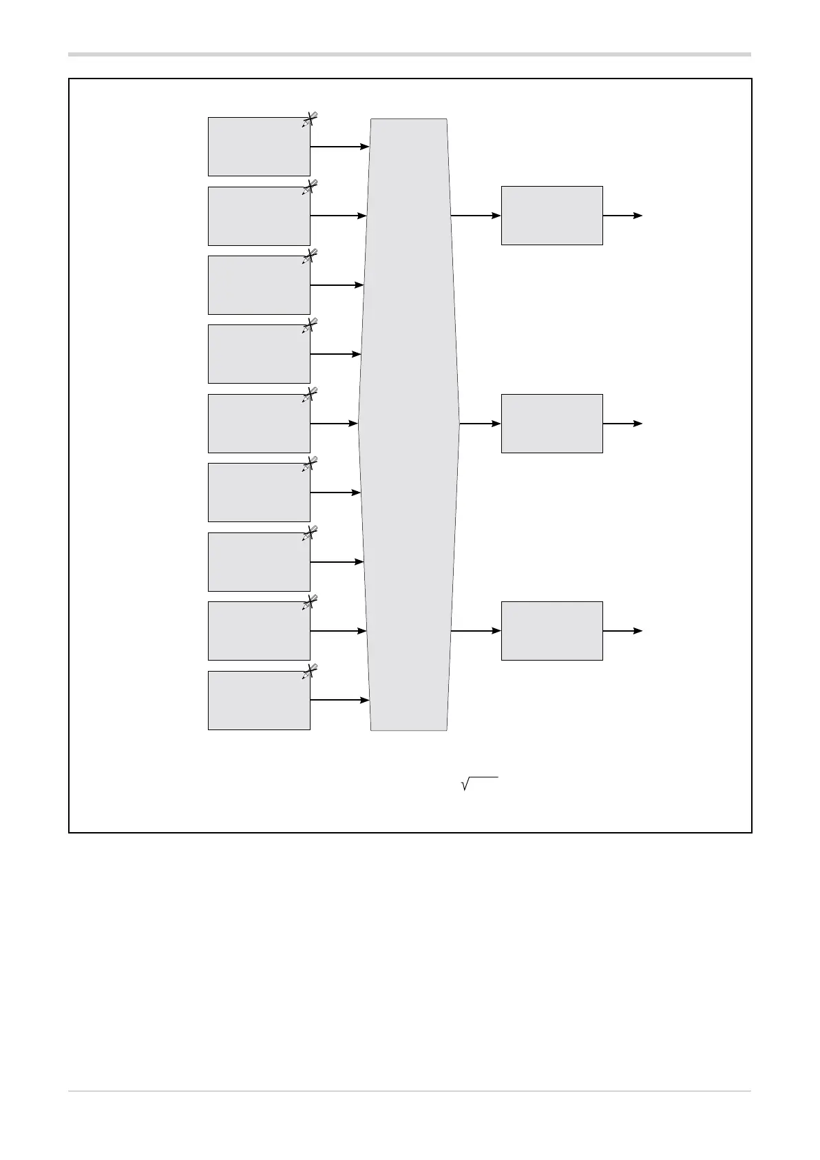
Functional diagram of HB alarm three-phase load
Note
The Hb.tr threshold value of the HB alarm is calculated in two different ways, depending on the chosen operating mode:
• with ZC, BF, HSC operating modes: Hb.tr = A.Hb
• with PA operating mode: Hb.tr = A.Hb * (Ou.P)
------------------------------------------------ OUTPUTS ------------------------------------------------
HB alarm
function
Hb.F
and
HB alarm
activation time
Hb.t
Alarm threshold
HB.tr_2
Filtered VT
voltmeter input
value
I.VF_1
Filtered CT ammeter
input value with
output 1 activated
I.on_1
Alarm threshold
HB.tr_1
HB alarm status
phase 1
HB alarm status
phase 2
HB alarm status
phase 3
Filtered CT ammeter
input value with
output 2 activated
I.on_2
Filtered VT
voltmeter input
value
I.VF_2
Alarm threshold
HB.tr_3
Filtered CT ammeter
input value with
output 3 activated
I.on_3
Filtered VT
voltmeter input
value
I.VF_3