81901 “MSW_GPC-40/600A”_03-2021_ENG_page 40
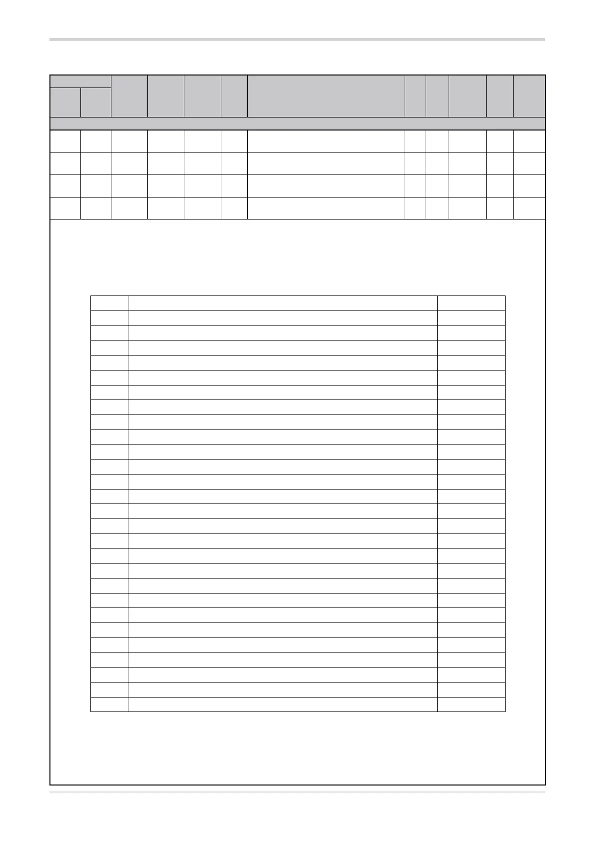
3.12.4. Digital input function
Address
Format
GPC-OP
menu
Acronym
Global /
M/E1/E2
GF_eXpress menu
Attribute
Retentive
Type
Unit of mea-
surement
Default
Single-
node
Multi-
node
Description
1164 140 16 bit 04:17:01 dIG.1 Global
MainMenu → Global → Inputs →
Digital inputs → dIG.1
R/W
■
Unsigned
Short
0
1642 618 16 bit 04:17:02 dIG.2 Global
MainMenu → Global → Inputs →
Digital inputs → dIG.2
R/W
■
Unsigned
Short
0
1718 694 16 bit 04:17:03 dIG.3 Global
MainMenu → Global → Inputs →
Digital inputs → dIG.3
R/W
■
Unsigned
Short
0
1736 712 16 bit 04:17:04 dIG.4 Global
MainMenu → Global → Inputs →
Digital inputs → dIG.4
R/W
■
Unsigned
Short
128
This parameter sets the function associated with digital input 1, 2, 3 or 4, depending on the address used. The input can be activated by a
change in value (“On leading edge”) or by its state (“On state”).
Each main function is identified by an index. By adding a fixed value to the index, the functions are thus modified:
+16 = input in denied logic
+32 = logic state 0 (OFF) is forced
+64 = logic state 1 (ON) is forced
Options:
Index Description Activation
0 No function (input disabled) On leading edge
1 MAN / AUTO controller On leading edge
4 Generic alarm memory reset AL1...AL8 On state
6 Software ON/OFF On leading edge
7 PWM * input On leading edge
10 Reset POWER_FAULT alarm memory On leading edge
12 AL1...AL8 and POWER_FAULT generic alarm memory reset On state
13 Enable software startup ** On state
14 Reference calibration of feedback selected by hd.6 On leading edge
15 HB alarm threshold calibration On leading edge
64 FUSE_OPEN / SHORT_CIRCUIT_CURRENT alarm reset On state
65 Reference calibration of feedback selected by hd.6 for GPC-M On leading edge
66 Reference calibration of feedback selected by hd.6 for GPC-E1 On leading edge
67 Reference calibration of feedback selected by hd.6 for GPC-E2 On leading edge
68 Calibration of HB alarm threshold for GPC-M On leading edge
69 Calibration of HB alarm threshold for GPC-E1 On leading edge
70 Calbiration of HB alarm setpoint for GPC-E2 On leading edge
71 MAN / AUTO for GPC-M On leading edge
72 MAN / AUTO for GPC-E1 On leading edge
73 MAN / AUTO for GPC-E2 On leading edge
74 ON / OFF Software for GPC-M On leading edge
75 ON / OFF Software for GPC-E1 On leading edge
76 ON / OFF Software for GPC-E2 On leading edge
77 Trigger change for GPC-M On state
78 Trigger change for GPC-E1 On state
79 Trigger change for GPC-E2 On state
128 Interlock On state
*) only for dIG.1 (PWM1, max 100 Hz), dIG.2 (PWM2, max1Hz), dIG.3 (PWM3, max 1 Hz)
**) only for dIG.1
Examples
Setting value “4” activates the cancellation function of alarms AL.1...AL.8 (e.g., by closing the digital input); by setting 20 (=4+16) the
AL.1...AL.8 alarm cancellation occurs with denied logic (e.g., by opening the digital input).