Home
Honeywell
Matrix Switcher
VideoBloX
Honeywell VideoBloX User Manual
4
of 1
of 1 rating
180 pages
Give review
Manual
Specs
To Next Page
To Next Page
To Previous Page
To Previous Page
Loading...
Honeywell
129
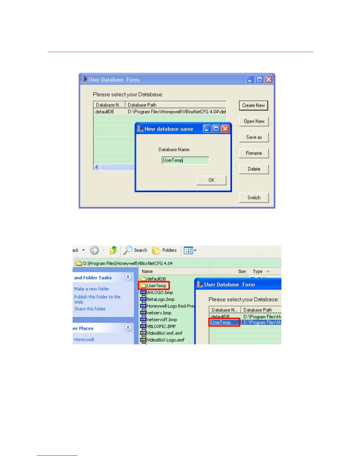
Figure 3-70 Create new data base
And then this database will b
e display in the database list and user
can find a fold with
the same name in the path where CFG had be
en installed.
Figure 3-71 Position of
new data b
ase
Than user can ch
oose the da
tabase ‘UserTemp’, and
press Switch button
to choose this
database.
144
146
Table of Contents
Default Chapter
4
Important Safeguards
4
Explanation of Graphical Symbols
6
Table of Contents
7
Introduction
17
Product Description
17
Figure 1-1 Front View of VB Chassis
17
System Overview
18
Rack Mount System Chassis
18
Figure 1-2 Rear View of VB Chassis
19
Videoblox Modules
20
Vb Chassiss Connections
20
Main Input Power Connection
20
Figure 2-1 Rear View of Videoblox Chassis' Main Power
20
Low Voltage Input Connection
21
Chassis Sync in
21
Control Expansion Connector
21
Communications Expansion Connector
21
Power Supply Module
22
DIP Switch Settings
22
Figure 2-2 DIP Switches of Power Supply Module
22
Reset Push Button
23
Indications
23
Sync Phase Adjustment
23
Chassis Expansion Driver Board
23
Netcpu & Netosd Module
24
Figure 2-3 Front and Rear Views of CPU Module
24
Jumper Settings
25
DIP Switch Settings
26
Figure 2-4 Jumpers Settings - Enable the NETCPU
26
Figure 2-5 Jumpers Settings - Enable the NETOSD
26
Figure 2-6 DIP Switches of HVBNET16CPU
27
Output Group Address
28
Figure 2-7 Six Push Buttons
29
Figure 2-8 Diagnostics LED
29
LED Indications
29
Push Buttons
29
Connections
30
Firmware Upgrade
30
Fuse
30
Figure 2-10 HVBNETCPU Homepage
31
Figure 2-9 Login Page
31
Figure 2-11 Configuring Network Connections
32
Figure 2-12 Changing Network Connection Setting
32
Figure 2-13 Confirming Network Connections
33
Figure 2-14 Upgrading NETCPU Firmware
33
Figure 2-15 Selecting NETCPU Upgrade File
34
Figure 2-16 Upgrade in Progress
34
Figure 2-17 Upgrade Completed
35
Figure 2-18 Changing Password
35
Figure 2-19 Changing Password Success
36
Figure 2-20 Login Page
36
Figure 2-21 HVBNETOSD Homepage
37
Figure 2-22 Configuring Network Connections
37
Figure 2-23 Selecting Language
38
Figure 2-24 Selecting Upgrade File
38
Figure 2-25 Start Upgrade
39
Video Input Modules
40
Figure 2-26 Software Version
40
DIP Switch Settings
41
Figure 2-27Video Input Modules (2 Front Panel Options)
41
Figure 2-28 Video Input Module (Standard - 16 BNC Inputs)
41
Figure 2-29 Video Input Module (Looping BNC Inputs)
41
Figure 2-30 Type A, B and C Cross-Connect Looping Input Terminal Modules
41
Figure 2-31 HVBM64 DIP SW Settings
42
Connections
43
Fuse
43
LED Indications
43
Video Output Modules
43
Titled Video Output Module
43
Figure 2-32 16 Channel Video Output Modules - Front View
43
Figure 2-33 16 Channel Video Output - Rear View
43
DIP Switch Settings
44
Figure 2-34 the Titled Video Output Module - Front View
44
Figure 2-35 the Titled Video Output Module - Rear View
44
Figure 2-36 Output Position Selections
44
Figure 2-37 Select Different 16 Outputs Group through Plug-In Board
45
Figure 2-38 Select Video Output 1-16 (Position a and B)
45
Module Board Setting, Video Outputs 1-16
45
Module Board Setting, Video Outputs 1-64
45
Figure 2-39 Select Video Output 17-32 (Position E and F)
46
Figure 2-40 Select Video Output 33-48 (Position C and D)
46
Module Board Setting, Video Outputs 17-32
46
Module Board Setting, Video Outputs 33-48
46
Module Board Setting, Video Outputs 49-64
47
Audio Input Module
47
Figure 2-41 Select Video Output 49-64 (Position G and H)
47
Figure 2-42 Front and Rear Views of Audio Input Module
47
Figure 2-43 Front and Rear Views of Audio Input Module (RJ45)
47
DIP Switch Settings
48
Figure 2-44 Pin of RJ45
48
PIN out of RJ45 Termination
48
Figure 2-45 DIP SW Setting of Audio Input Module
49
Figure 2-46 20Db Jumper Selection
49
Jumpers Settings
49
Adjustments
50
Connecting a Microphone to the Audio Input Module
50
Figure 2-47 Jumper Setting for Low Pass or High Pass Filter
50
Figure 2-48 CMRR Adjustment
50
Audio Output Module
51
Figure 2-49 Diagram of Connecting a Microphone
51
Figure 2-50 Front and Rear Views of 8 and 16 Channel Audio Output Modules
51
Chassis Interlink Input and Output Module
52
Figure 2-51 Chassis Interlink Output Module
52
Figure 2-52 Chassis Interlink Input Module
52
DIP Switch Settings
53
Figure 2-53 Back Plane Video Channels Selection for Interlink Input Module
53
Figure 2-54 DIP SW Settings for Interlink Input Module
53
Figure 2-55 SW1 and SW2 Settings for Interlink Input Module
53
Figure 2-56 SW 3 and SW 4 Settings for Interlink Input Module
55
System Configuration
56
Overview
56
Planning Your System
56
Netcpu System Configuration Buttons
57
Figure 3-1 Initial Configuration Screen
57
System
58
Figure 3-2 System Configuration
58
License
59
Utilities Button Definitions
59
Figure 3-3 System-License Configuration
60
Sizing
60
Figure 3-4 System-Sizing Configuration
61
Date/Time
62
Figure 3-5 System-Date/Time Configuration
62
Communications
64
Figure 3-6 System-Communications Configuration
64
Installer
64
INPUTS (Adding a Video Input)
65
Inputs Detail
65
Figure 3-7 System-Installer Configuration
65
Figure 3-8 Inputs - Detail Configuration
66
Input Title
68
Figure 3-9 Inputs - Titles Configuration
69
Input Access
71
Figure 3-10 Inputs - Access Configuration
71
Input Group Names
72
Figure 3-11 Inputs - Group Names Configuration
73
Links (Setting Satellite)
74
Figure 3-12 Inputs - Group Names Configuration
74
OUTPUTS (Adding a Video Output)
75
Outputs Detail
75
Figure 3-13 Outputs - Detail Configuration
76
Output Access
77
Figure 3-14 Outputs - Access Configuration
78
Output Group Names
79
Figure 3-15 Outputs - Group Names Configuration
79
Scenes
80
Figure 3-16 Scenes Configuration
80
Groups
81
Figure 3-17 Groups Configuration
82
Alarms
83
Alarm Configuration
83
Figure 3-18 Alarms - General Configuration
84
Alarms Access
86
Figure 3-19 Alarms - Access Configuration
87
Alarm Group Names
88
Figure 3-20 Alarms - Group Names Configuration
88
Alarmq (Alarm Queues)
89
Alarm Queue Configuration
89
Figure 3-21 Alarms Queues Configuration
90
Users
93
Users Detail
93
Figure 3-22 Users - Detail Configuration
93
User Keys
95
Figure 3-23 Users - Keys Configuration
96
Users Access
97
Figure 3-24 Users - Access Configuration
98
Users Notes
99
Figure 3-25 Users - Notes Configuration
99
Keyboards
100
Keyboards Detail
100
Figure 3-26 Keyboards - Detail Configuration
100
Keyboard Keys
104
Figure 3-27 Keyboards - Keys Configuration
104
Keyboard Access
105
Figure 3-28 Keyboards - Access Configuration
106
Keyboard Notes
107
Keyboard Group Names
108
Figure 3-29 Keyboards - Notes Configuration
108
Figure 3-30 Keyboards - Group Names Configuration
109
Keyboard Functionality
110
Figure 3-31 KEYBOARD MODE
110
Figure 3-32 Login Mode
111
Figure 3-33 Camera Mode
111
Figure 3-34 Camera Mode
112
Figure 3-35 Monitor Mode
112
Figure 3-36 High Speed Dome Mode
113
Figure 3-37 PTZ Mode
113
Figure 3-38 Preset Recall
114
Figure 3-39 Preset Store
114
Figure 3-40 High Speed Dome (Auxiliaries)
115
Figure 3-41 Group/Scene Mode
115
Figure 3-42 Device Control Mode
116
Figure 3-43 Sanyo VCR Control
116
Figure 3-44 VST DVR Control
117
Tods (Time of Day Events)
118
Event Configuration
118
Figure 3-45 Honeywell Ademco MUX Control
118
Figure 3-46 Tods Configuration
119
Message
120
Overview
120
Message Configuration
121
Figure 3-47 Message Configuration
121
Sequence
122
Sequences Overview
122
Sequences Editor
123
Figure 3-48 Sequences - Editor Configuration
123
Sequences Notes
125
Sequences Access
126
Figure 3-49 Sequences - Notes Configuration
126
Figure 3-50 Sequences - Access Configuration
127
Sequences Group Names
128
Figure 3-51 Sequences - Group Names Configuration
128
Sequence Examples
129
Figure 3-52 Sequences Configuration Example - Camera Switching Sequence
130
Sequence Engine Commands
131
Figure 3-53 Sequences Configuration Example - Camera Preset Sequence
131
Devices
133
Peripheral Devices Configuration
133
Figure 3-54 Device - General Configuration
134
Device Access
135
Figure 3-55 Device - Access Configuration
135
Device Group Names
136
Figure 3-56 Device - Group Names Configuration
136
Device Control Configuration
137
Figure 3-57 PCKZ-CAS Keyboard
137
Figure 3-58 Videoblox Device Control Configuration
138
Figure 3-59 User Keys on Software and Keyboard
138
Figure 3-60 Function Keys on Software and Keyboard
138
Figure 3-61 Extended Function Keys on Software and Keyboard
139
Figure 3-62 Arrow Keys on Software and Keyboard
139
Figure 3-63 the Display Textbox
140
Figure 3-64 Clicking on the Button to be Configured
140
Figure 3-65 Key Press Configuration
140
Figure 3-66 Key Configuration Result
141
Figure 3-67 Control Configuration
141
Database
143
Figure 3-68 Open Data Base
143
Figure 3-69 Choose Base
144
Figure 3-70 Create New Data Base
145
Figure 3-71 Position of New Data Base
145
Figure 3-72 Switch Data Base
146
Figure 3-73 Data Base Prompt
146
Figure 3-74 Open Other Data Base
147
Videoblox Applications
148
Interfacing Hvbnetcpu with Peripheral Devices
148
Figure 4-1 Interfacing HVBNETCPU with Peripheral Devices
148
Interfacing Hvbnetcpu with Gui Work-Stations on Anetwork
149
Figure 4-2 Interfacing HVBNETCPU with GUI Work-Station
149
Interfacing Hvbnetcpu with Satellite Systems on Anetwork
150
Video on Fiber
150
Figure 4-3 Interfacing HVBNETCPU with Satellite System with Video on Fiber
150
Video on IP
151
Figure 4-4 Interfacing HVBNETCPU with Satellite System with Video on IP
151
Integrating Enterprise DVR and Satellite Videoblox
152
Figure 4-5 Integrating Enterprise DVR and Satellite Videoblox
152
System Benefits
153
Appendix A: Videoblox Chassis Interlink Expansion
154
Introduction
154
Interlink Input and Output Modules
154
Figure 5-1 HVBLKI Module
154
Chassis Expansion Connection and Dip Switch Setting
155
Figure 5-2 HVBLKO Module
155
Figure 5-3 Backplane Control and Communications of VB Chassis
156
Figure 5-4 Dip Switch of VB Chassis
156
Example : 784 Inputx 64 Output System Configuration
157
HVB32LKO Jumper Setting
157
Figure 5-5 784 Input X 64 Output System Configuration
157
HVB32LKI Jumper and Dip Switch Setting
158
Figure 5-6 HVB32LKO Jumper Setting
158
Figure 5-7 HVB32LKI Jumper and Dip Switch Setting
158
Figure 5-8 Inter-Link Start and End Address of 1
159
Rj45 Cable Connection
160
Figure 5-9 Inter-Link Start and End Address of 2
160
Appendix B: Backward Compatible Application
161
Introduction
161
I Nterface New Input Module with Old System
161
Figure 6-1 HVBM64 Jumper Position
161
Interface New Output and Titled Output Module with Old System
162
Interface New Cpu Module with Old System
162
Figure 6-2 Buffer Board of HVBNET16TO
162
Appendix C: Aux Command List
164
Appendix D: Sequence Command Examples
168
Other manuals for Honeywell VideoBloX
Quick Start Guide
38 pages
4
Based on 1 rating
Ask a question
Give review
Questions and Answers:
Need help?
Do you have a question about the Honeywell VideoBloX and is the answer not in the manual?
Ask a question
Honeywell VideoBloX Specifications
General
Brand
Honeywell
Model
VideoBloX
Category
Matrix Switcher
Language
English
Related product manuals
Honeywell HMAX082
116 pages
 Loading...